Circuit board assembly method
An assembly method and circuit board technology, which is applied in the direction of assembling printed circuits with electrical components, can solve problems such as manual labor, design that cannot meet the wave peak, and direct wave soldering, etc., so as to improve the efficiency of soldering and increase the market Application value, effect of saving assembly manpower
- Summary
- Abstract
- Description
- Claims
- Application Information
AI Technical Summary
Problems solved by technology
Method used
Image

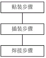
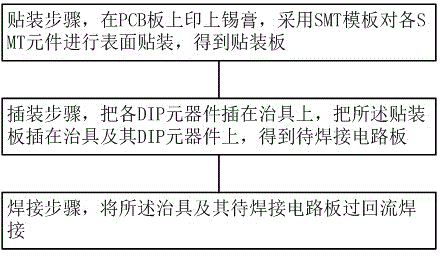
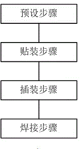
Examples
Embodiment Construction
[0028] In order to facilitate the understanding of the present invention, the present invention will be described in more detail below in conjunction with the accompanying drawings and specific embodiments. Preferred embodiments of the present invention are given in the description and drawings, but the present invention can be implemented in many different forms and is not limited to the embodiments described in the description. On the contrary, these embodiments are provided to make the understanding of the disclosure of the present invention more thorough and comprehensive.
[0029] It should be noted that when a certain component is fixed to another component, it includes directly fixing the component to the other component, or fixing the component to the other component through at least one other component in the middle . When a component is connected to another component, it includes directly connecting the component to the other component, or connecting the component t...
PUM
 Abstract
Description
Claims
Application Information
 - Generate Ideas
- Intellectual Property
- Life Sciences
- Materials
- Tech Scout
- Unparalleled Data Quality
- Higher Quality Content
- 60% Fewer Hallucinations
Browse by: Latest US Patents, China's latest patents, Technical Efficacy Thesaurus, Application Domain, Technology Topic, Popular Technical Reports.
© 2025 PatSnap. All rights reserved.Legal|Privacy policy|Modern Slavery Act Transparency Statement|Sitemap|About US| Contact US: help@patsnap.com