Methods of producing flexible pipe bodies, and flexible pipe bodies

A flexible pipe and main body technology, applied in the direction of pipes/pipe joints/fittings, pipes, hoses, etc., can solve the problems of pipe layer damage, pipe layer heating, etc., achieve high strength and life, improve flexibility, and improve coilability Effect

Inactive Publication Date: 2014-11-19
GE OIL & GAS UK LTD
View PDF3 Cites 4 Cited by
  • Summary
  • Abstract
  • Description
  • Claims
  • Application Information

AI Technical Summary

Problems solved by technology

However, this technique can cause damage to the outside of the tube layer, while the inside of the tube layer is not sufficiently heated

Method used


Image

  • Methods of producing flexible pipe bodies, and flexible pipe bodies
  • Methods of producing flexible pipe bodies, and flexible pipe bodies
  • Methods of producing flexible pipe bodies, and flexible pipe bodies

Examples


Embodiment Construction

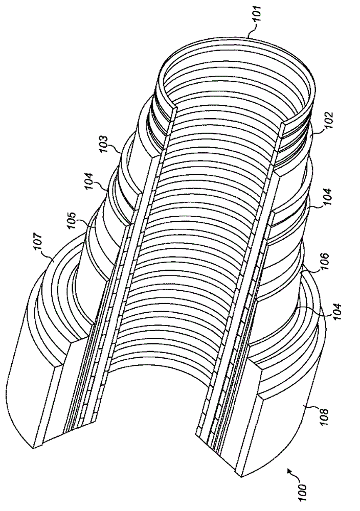
[0035] Throughout this description, reference will be made to flexible pipes. It should be understood that a flexible pipe is an assembly of a part of a pipe main body and one or more end fittings, and each of the end fittings terminates a corresponding end of the pipe main body. figure 1 It is shown how to form the pipe main body 100 according to an embodiment of the present invention from a combination of layered materials forming a pressure bearing pipe. Even though figure 1 A number of special layers are shown in, but it should be understood that the present invention is broadly applicable to coaxial tube body structures that include two or more layers made of a variety of possible materials. It should also be noted that the layer thicknesses are shown for illustrative purposes only.

[0036] Such as figure 1 As shown, the tube body 100 includes an optional innermost frame layer 101. The frame 101 provides an interlocking configuration that can be used as the innermost layer...


PUM


Abstract

A flexible pipe body and method of producing a flexible pipe body are disclosed. The method includes providing a length of composite material of thermoplastic or thermosetting material with an electrically conductive material dispersed therein, applying the length to a mandrel or a layer of flexible pipe body, and heating the length by induction heating using an induction heating coil to cure the thermoplastic or thermosetting material.

Description

Technical field [0001] The invention relates to a flexible pipe main body and a method for producing the flexible pipe main body. In particular, but not exclusively, the present invention relates to the use of a composite comprising a thermoplastic material or a thermosetting material and a conductive material for forming one or more layers of the pipe body. Background technique [0002] Traditionally, flexible pipes are used to transport production fluids (such as oil and / or gas and / or water) from one location to another. Flexible pipes are particularly suitable for connecting subsea locations (which can be deep underwater, for example 1000 meters or more) to sea level locations. The tube may have an inner diameter generally up to about 0.6 meters. The flexible pipe is generally formed as an assembly of a flexible pipe body and one or more end fittings. The pipe body is generally formed as a combination of layered materials that form a pressure bearing pipe. The tube structu...

Claims


Application Information

Patent Timeline
Patent Type & Authority Applications(China)
IPC IPC(8): B29C53/64B29C53/58B29C53/84F16L11/127
CPCB29D23/001B29C53/64B29C53/845F16L11/088F16L11/127F16L11/04B29C53/582
Inventor G.S.格雷厄姆
Owner GE OIL & GAS UK LTD
Why Eureka
Try Eureka