
Lighting module and method of manufacturing a lighting module

A technology for light-emitting modules and light-emitting surfaces, which is applied to semiconductor devices, light sources, lasers, etc.

Active Publication Date: 2014-11-19
SIGNIFY HLDG BV
View PDF4 Cites 0 Cited by
  • Summary
  • Abstract
  • Description
  • Claims
  • Application Information

AI Technical Summary

Problems solved by technology

[0006] However, the method of producing housings for each semiconductor chip is inefficient, complex and case-by-case
As a result, the manufactured product becomes relatively expensive

Method used


Image

  • Lighting module and method of manufacturing a lighting module
  • Lighting module and method of manufacturing a lighting module
  • Lighting module and method of manufacturing a lighting module

Examples


Embodiment Construction

[0043] In the following description, the invention is described with reference to a method of manufacturing a lighting module.

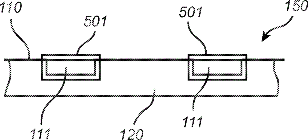
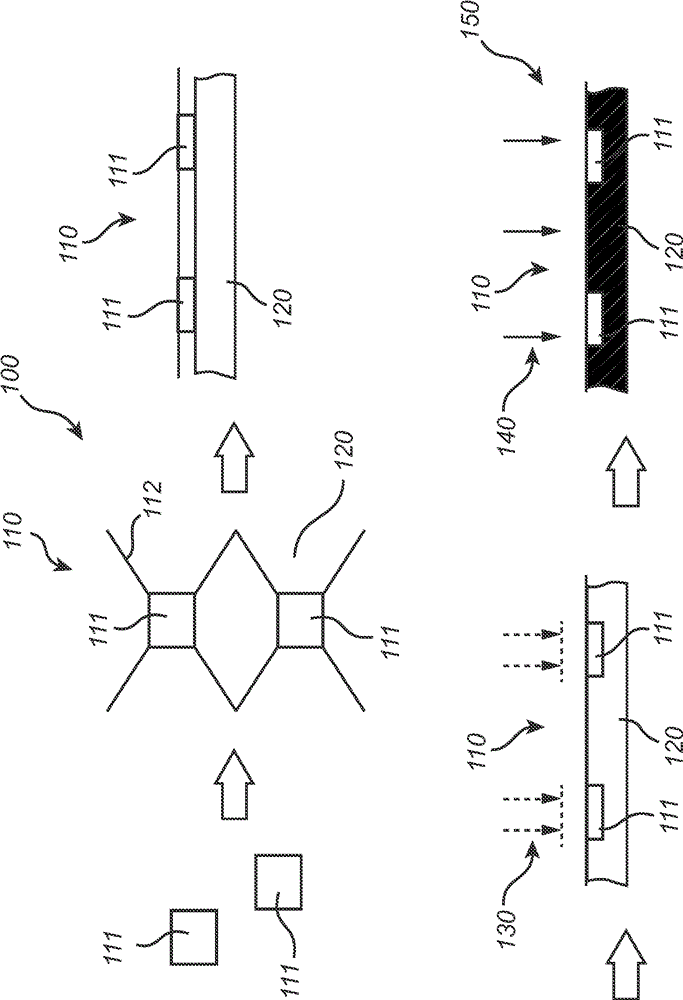
[0044] figure 1 is a schematic illustration of a method 100 for manufacturing a lighting module 150 . The method 100 includes the step of providing a light source assembly 110 comprising a plurality of light sources 111 (hereinafter denoted LEDs) electrically connected to a carrier 112 . Here, the carrier 112 is provided as a wire grid to which the LEDs 111 are connected, wherein the wire grid has a chicken wire shape. However, it will be appreciated that substantially any wire grid grid shape may be feasible. Each LED 111 has a light emitting (ie, light transmissive) surface on the top portion of the LED 111 . The method 100 further includes the step of providing a heat dissipation material 120 in a fluid state, wherein an example of the heat dissipation material 120 may be ceramic. Preferred ceramics are, for example, clay, concrete, quartz, po...


PUM


Abstract

A lighting module (150) and a method (100) of manufacturing a lighting module, wherein the method comprises the steps of providing a heat sink material (120) in a fluid state and providing a light-source assembly (110) comprising a plurality of light sources (111) being electrically connected to a carrier (112), wherein each of the light sources has a light-emitting surface (113). The method further comprises the steps of embedding (130) the light-source assembly into the heat sink material such that the carrier and a part of each of the light sources are covered by the heat sink material while the light-emitting surface of each of the light sources is uncovered by the heat sink material, and solidifying (140) the heat sink material.

Description

technical field [0001] The invention relates to a lighting module and to a method of manufacturing a lighting module. Background technique [0002] Common to light sources such as light emitting diodes (LEDs), light bulbs, laser diodes and lamps is that the light sources generate heat. A light emitting arrangement comprising a plurality of light sources (eg used in a display or in a lighting device) may generate a rapid rise in temperature of the light emitting arrangement, especially when many light sources are driven simultaneously. Thermal effects can be detrimental to the light sources, and their operation can become irregular and unstable. As a result, the light from the light source may flicker, causing a decrease in the quality of display or lighting. Therefore, thermal management is an important issue in preventing thermal damage to light sources, and it is necessary to dissipate excess heat in order to maintain the reliability of the lighting arrangement and preve...

Claims


Application Information

Patent Timeline
Patent Type & Authority Applications(China)
IPC IPC(8): H01L33/64H01S5/024H01L33/56H01L33/62H01L25/075
CPCH01L33/642H01L33/641H01L2924/0002H01L33/62H01L25/0753H01L33/56H01L33/644H01L2933/0075H01L2933/0066H01L2924/00F21S8/06F21Y2115/10F21K9/23F21K9/90F21V19/002F21V23/06
Inventor R.A.M.希克梅特T.范博姆梅J.余
Owner SIGNIFY HLDG BV
Learn More