
DNA sample collection and preservation device

A storage device and sample collection technology, which is applied in the field of nucleic acid DNA or RNA collection tools, can solve the problems of template loss, pollution, and external source background pollution, and achieve the effects of convenient carrying and storage, reducing use costs, and ensuring the detection rate

Active Publication Date: 2016-04-06
成都迪盾生物技术有限公司
View PDF8 Cites 0 Cited by
  • Summary
  • Abstract
  • Description
  • Claims
  • Application Information

AI Technical Summary

Problems solved by technology

[0003] Using cotton swabs to wipe and transfer contact biological samples that cannot be extracted from physical objects, such as blood stains, body fluids, sperm spots, and exfoliated cells, is currently a commonly used technical method, but there are the following technical problems in collecting samples with cotton swabs: One is that it is difficult to properly grasp the pinching position of the fingers on the cotton swab shaft. Therefore, if the pinching position is too far away from the cotton ball, it will be weak to wipe the contact biological material and even easily broken. If the pinching position is too close to the cotton ball , although the wiping force can be increased, there is a risk of exogenous background contamination of the test material due to direct contact between fingers or gloves and the test material, that is, exogenous pollution; Finally, it is usually placed in a kraft paper bag (used to be called an envelope) or similar evidence bag, so because the cotton ball is in direct contact with the bag, it is easy to cause template loss; third, because the cotton swab after sampling is dried in the shade in a closed paper bag, so The drying time in the shade is long and it is not conducive to reflecting the overall effect of drying in the shade; Fourth, the cotton swabs will also cause pollution due to carelessness during the carrying process before sampling, which will affect the sampling effect and ultimately affect the detection and analysis of DNA
But there is following shortcoming: one, owing to cotton swab and plug body are fixed, and plug body and tube body are fixed, thereby although can make cotton swab be in suspended state in the tube body cavity of tube body and avoid pollution and secondary transfer loss, but It is not convenient to use, because the plug (called the first plug body in the patent) needs to be removed from the tube body during use, and the plug and the cotton swab are removed from the tube body. After the sample collection, the plug and the cotton swab are returned to the tube body cavity, especially In the process of removing the plug and the cotton swab from the tube body and returning to the tube body cavity, once the operation is not careful, the cotton swab will come into contact with the wall of the tube body, and there is a risk of background contamination from external sources; secondly, due to the need to rely on The desiccant dries the cotton swab, so an isolation grid and a plug (the patent is called the second plug body) are arranged at the end of the tube body facing the cotton ball, and a desiccant is placed in the space formed between the plug and the isolation grid. , so not only the structure is complicated, but also the cost is high, because this device is usually disposable; third, because the cavity where the desiccant is set, that is, the desiccant cavity must pass through the hole on the isolation screen and the cotton swab cavity (that is, the aforementioned tube body cavity) ) are interlinked, so once the desiccant crumbs of the desiccant enter the cotton swab cavity, it will undoubtedly cause pollution

Method used


Image

  • DNA sample collection and preservation device
  • DNA sample collection and preservation device
  • DNA sample collection and preservation device

Examples


Embodiment Construction

[0024] In order to enable the examiners of the patent office, especially the public, to understand the technical essence and beneficial effects of the present invention more clearly, the applicant will describe in detail the following in the form of examples, but none of the descriptions to the examples is an explanation of the solutions of the present invention. Any equivalent transformation made according to the concept of the present invention which is merely formal but not substantive shall be regarded as the scope of the technical solution of the present invention.

[0025] In the following descriptions, all concepts related to the directionality (or orientation) of up, middle, down, left, right, front and back are for the position state of the picture being described, and the purpose is to It is convenient for the public to understand, so it cannot be understood as a special limitation on the technical solution provided by the present invention.

[0026] See figure 1, a...


PUM


Abstract

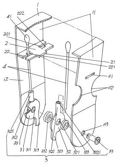
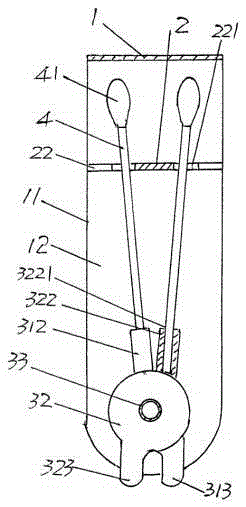
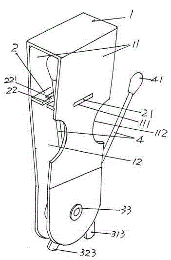
The invention discloses a DNA sample collection and preservation device, and belongs to the technical field of nucleic acid DNA or RNA collection tools. The DNA sample collection and preservation device comprises a cotton swab protection clamp, a cotton swab bearing and limiting plate and a cotton swab pivotal bearing mechanism. The cotton swab protection clamp is provided with a pair of corresponding protection clamp arms, the cotton swab bearing and limiting plate is arranged between the protection clamp arms and on the upper portions of the protection clamp arms, the cotton swab pivotal bearing mechanism is used for unfolding cotton swabs out of a cotton swab protection clamp cavity of the cotton swab protection clamp or returning the cotton swabs to the cotton swab protection clamp cavity, and the cotton swab pivotal bearing mechanism is arranged between the protection clamp arms, and is arranged on the lower portions of the protection clamp arms. Biomaterials on the cotton swabs are prevented from being transferred the second time, and the detection rate of DNA in the subsequent detection process is guaranteed. The structure is simplified, manufacturing is convenient, and cost is lowered. Exogenous pollution is avoided, and therefore the quality of detecting materials can be guaranteed. Good practicality is achieved, and the device is convenient to carry and store.

Description

technical field [0001] The invention belongs to the technical field of nucleic acid DNA or RNA collection tools, and in particular relates to a DNA sample collection and storage device. Background technique [0002] The detection of DNA is of positive significance in the fields of medical treatment, criminal case investigation, identification of victims of accidents and natural disasters, archaeology, and in the field of animal and plant inspection and quarantine. However, sampling must be carried out before DNA detection, that is, DNA sampling It is the premise of detection, otherwise detection will become water without source and tree without roots. [0003] Using cotton swabs to wipe and transfer contact biological samples that cannot be extracted from physical objects, such as blood stains, body fluids, sperm spots, and exfoliated cells, is currently a commonly used technical method, but there are the following technical problems in collecting samples with cotton swabs: ...

Claims


Application Information

Patent Timeline
Patent Type & Authority Patents(China)
IPC IPC(8): A61B10/02G01N1/02
Inventor 齐洁丽
Owner 成都迪盾生物技术有限公司
Learn More