Supercharge Your Innovation With Domain-Expert AI Agents!

Tin bar casting shaping device

A technology of tin bars and air pumps, which is applied to the equipment for feeding molten metal into molds, manufacturing tools, metal processing equipment, etc. It can solve the problems of complex structure, high price, cumbersome maintenance and operation, and achieve cost reduction. Low cost, simplified structure, convenient maintenance and operation

Active Publication Date: 2014-11-26
浙江强力控股有限公司
View PDF6 Cites 2 Cited by
  • Summary
  • Abstract
  • Description
  • Claims
  • Application Information

AI Technical Summary

Problems solved by technology

[0002] The solder bar pouring and molding device currently on the market mainly includes a base, a casting mold, a guide column, a beam that slides up and down along the guide column, and the bottom wall of the beam is provided with a stamping product logo and a pressing mold; an air pump fixed to the column is arranged above the beam , used to drive the beam to move up and down; due to the long-term use of the stamper, the gaps in the pattern are easy to be filled by solder during stamping, resulting in the embossed pattern not meeting the sales requirements, so the stamper needs to be cleaned frequently. The disadvantage of this traditional solder rod pouring and molding device is that it is limited by its own structure, which leads to more cumbersome maintenance operations; in addition, due to its more complicated structure, its price remains high

Method used


Image

  • Tin bar casting shaping device
  • Tin bar casting shaping device
  • Tin bar casting shaping device

Examples


Embodiment 1

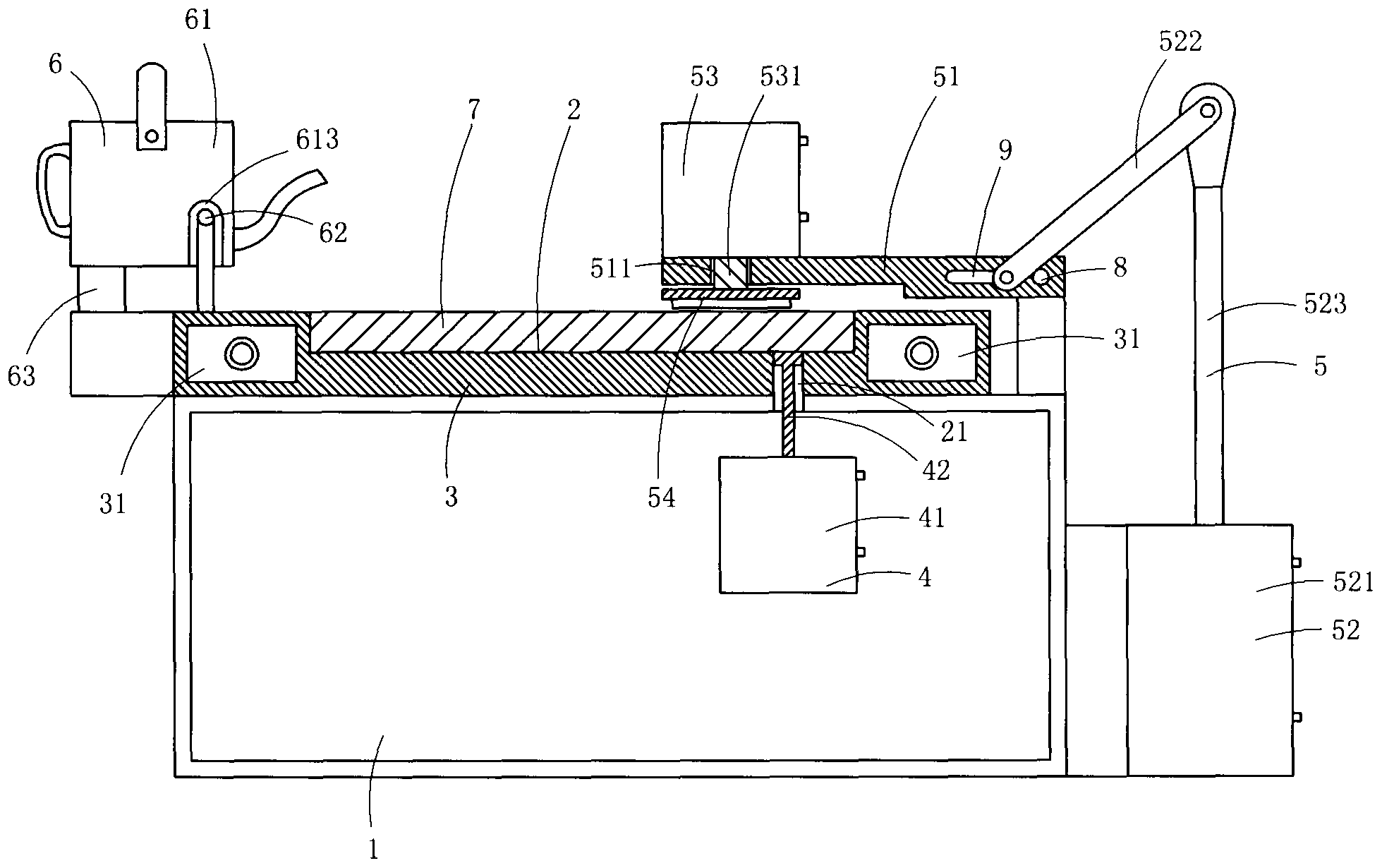
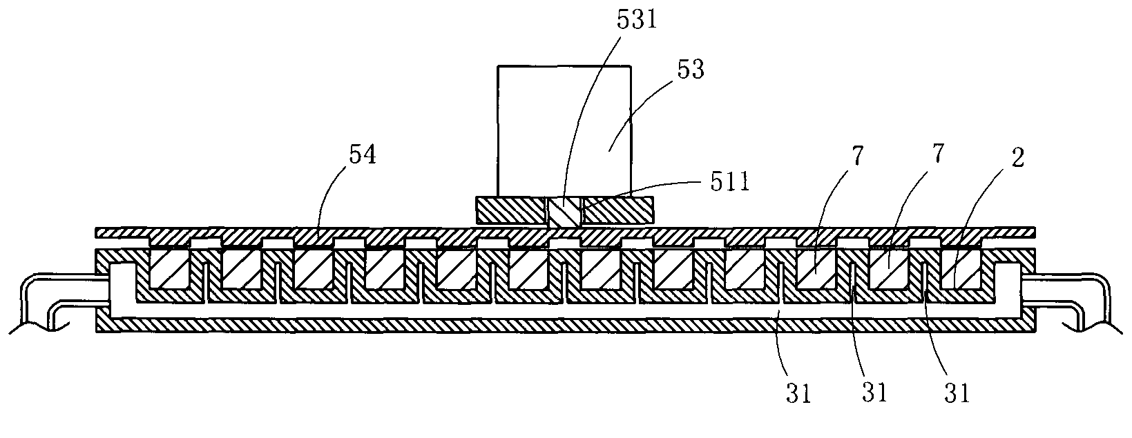
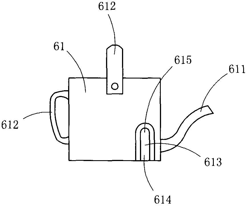
[0012] Figure 1 to Figure 4 A specific embodiment of the invention is shown in which, figure 1 It is a structural schematic diagram of the present invention; figure 2 yes figure 1 A structural schematic diagram of the embossing mechanism and the casting mold in the shown tin bar pouring and molding device; image 3 yes figure 1 A schematic diagram of the structure of the tin pot in the tin bar pouring and molding device shown; Figure 4 yes image 3 A top view structure schematic diagram of the shown tin pot.

[0013] This embodiment is a casting and molding device for tin bars, comprising a base 1, a mold 3 provided with twelve pouring grooves 2, an ejection mechanism 4 for ejecting shaped tin bars from the pouring grooves, Embossing mechanism 5 and pouring mechanism 6 that emboss patterns on the shaped tin bar. For clarity of description, tin strips 7 are also drawn in the accompanying drawings. Graphics and texts as product identification are arranged on the botto...


PUM


Abstract

The invention discloses a tin bar casting shaping device. The tin bar casting shaping device comprises a base, a casting mould with a plurality of casting profiled grooves, an ejecting mechanism used for ejecting formed tin bars out of the casting profiled grooves and an impressing mechanism used for impressing patterns on the formed tin bars. The impressing mechanism comprises a bearing plate arranged on the base in a rotating mode, a first air pump assembly used for driving the bearing plate to rotate, a second air pump fixedly arranged above the bearing plate, and a pressing mould arranged below the bearing plate and used for impressing the patterns. The bearing plate is provided with a through hole, and a piston rod of the second air pump penetrates through the through hole to be fixedly connected with the pressing mould. The tin bar casting shaping device has the advantages of being simplified in structure, low in cost and convenient to overhaul and maintain.

Description

technical field [0001] The invention belongs to the technical field of solder bar processing and manufacturing, and in particular relates to a tin bar pouring and molding device. Background technique [0002] The solder bar pouring and molding device currently on the market mainly includes a base, a casting mold, a guide column, a beam that slides up and down along the guide column, and the bottom wall of the beam is provided with a stamping product logo and a pressing mold; an air pump fixed to the column is arranged above the beam , used to drive the beam to move up and down; due to the long-term use of the stamper, the gaps in the pattern are easy to be filled by solder during stamping, resulting in the embossed pattern not meeting the sales requirements, so the stamper needs to be cleaned frequently. The disadvantage of this traditional solder rod pouring and molding device is that it is limited by its own structure, resulting in cumbersome maintenance operations; in add...

Claims


Application Information

Patent Timeline
Patent Type & Authority Applications(China)
IPC IPC(8): B22D27/04B22D35/04B22D29/06
Inventor 赵图强
Owner 浙江强力控股有限公司
Features
  • R&D
  • Intellectual Property
  • Life Sciences
  • Materials
  • Tech Scout
  • Unparalleled Data Quality
  • Higher Quality Content
  • 60% Fewer Hallucinations
Learn More