Dustproof pipeline structure for spinning dust removal

A pipe and dust collection pipe technology, which is applied in the field of dust removal pipes in textile workshops, can solve the problems of affecting the dust removal effect, low dust removal efficiency, cumbersome cleaning and replacement operations, etc., to achieve good cleaning effect, improve filtering effect, and shorten cleaning and replacement cycle effect

Inactive Publication Date: 2014-11-26
SUZHOU KAIFENGRUI ELECTRONICS SCI & TECHCO
View PDF5 Cites 1 Cited by
  • Summary
  • Abstract
  • Description
  • Claims
  • Application Information

AI Technical Summary

Problems solved by technology

In order to avoid affecting the dust removal effect, the filter in the dust removal pipeline needs to be manually cleaned or replaced regularly, and the cleaning and replacement operations are cumbersome, resulting in low dust removal efficiency

Method used


Image

  • Dustproof pipeline structure for spinning dust removal
  • Dustproof pipeline structure for spinning dust removal

Examples


Embodiment Construction

[0014] The specific implementation manner of the present invention will be described below in conjunction with the accompanying drawings.

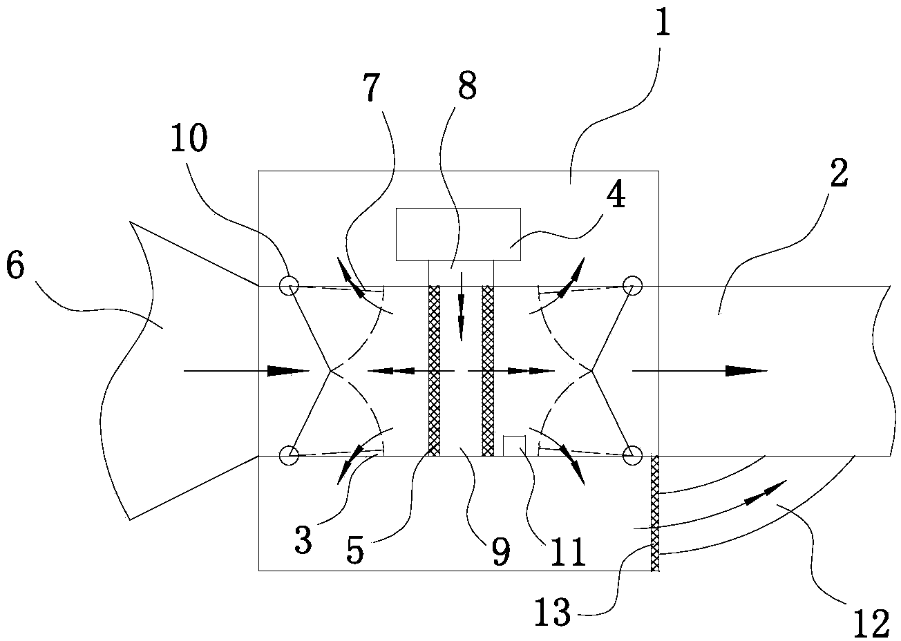
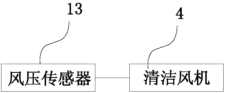
[0015] Such as figure 1 and figure 2 As shown, the dust removal pipeline structure used for textile dust removal in this embodiment includes the filter sheet 5 installed between the air collection pipe 6 and the air pipe 2, and the filter sheet 5 is installed in parallel between the air collection pipe 6 and the air pipe 2, and the two filters There is an anti-dust removal gap 9 between the sheets 5; a cleaning fan 4 is installed on the outer wall of the air duct 2, and the air guide pipe 8 of the cleaning fan 4 communicates with the anti-dust removal gap 9; the side walls of the air duct 2 on both sides of the filter sheet 5 are symmetrical There is a dust guide door 7, one end of the dust guide door 7 is respectively connected to the air duct 2 by means of a spring buckle 10, and an opening gap 3 is maintained between the other end and...


PUM


Abstract

The invention relates to a dustproof pipeline structure for spinning dust removal. The dustproof pipeline structure comprises filters which are arranged between an air collection pipe and an air pipe in parallel. A reverse dedusting gap is formed between the two filters. A cleaning fan is mounted on the outer wall of the air pipe. An air guide pipe of the cleaning fan is communicated with the reverse dedusting gap. The side walls, on the two sides of the filters, of the air pipe are respectively provided with a dust guide door, and the dust guide doors are symmetric. One end of each dust guide door is connected with the air pipe through a spring, and an opening gap is kept between the other end of each dust guide door and the air pipe. A dust collection pipe is further arranged on the outer wall of the air pipe. The dust collection pipe is communicated with the air pipe through a connecting pipe. A dustproof filter plate is arranged between the dust collection pipe and the connecting pipe. A wind pressure sensor is mounted on the inner wall of the air pipe between the filters and a dust removing device. The wind pressure sensor controls the cleaning fan by detecting the magnitude of wind pressure. The dustproof pipeline structure shortens the replacement and cleaning cycle of the filters and improves dust removal efficiency.

Description

technical field [0001] The invention relates to the field of dust removal equipment, in particular to a dust removal pipeline of a textile workshop. Background technique [0002] The current cotton textile industrial engineering mainly uses machinery to process fiber materials. In the process of processing, cotton dust, fiber debris, dust and other sundries will inevitably be produced. Avoid bringing debris and garbage from outside the workshop, causing environmental pollution in the workshop, which not only endangers the health of the staff, but also affects product quality. [0003] Usually, dust removal equipment is relied on in textile workshops. In the dust removal equipment, a filter is generally installed in the dust removal pipe to prevent dust from entering the fan of the dust collector. In order to avoid affecting the dust removal effect, the filters in the dust removal pipeline need to be manually cleaned or replaced regularly, and the cleaning and replacement o...

Claims


Application Information

Patent Timeline
Patent Type & Authority Applications(China)
IPC IPC(8): D01H11/00
Inventor 不公告发明人
Owner SUZHOU KAIFENGRUI ELECTRONICS SCI & TECHCO
Why Eureka
Try Eureka