
Cold recovery method for vaporization heat absorption-compression heat release coupling

A cooling capacity recovery and compressor technology, applied in the direction of machines/engines, mechanical equipment, etc., can solve the problems of large cooling capacity loss, complex recovery structure, and difficulty in cooling capacity recovery, so as to improve the heat exchange rate and increase the heat exchange rate. area, the effect of avoiding the use of large heat exchangers

Inactive Publication Date: 2014-11-26
BEIHANG UNIV
View PDF7 Cites 1 Cited by
  • Summary
  • Abstract
  • Description
  • Claims
  • Application Information

AI Technical Summary

Problems solved by technology

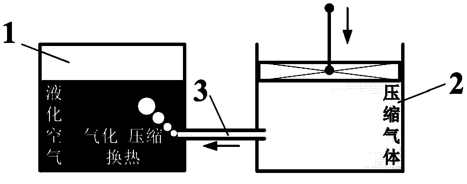
[0010] The method of directly injecting liquid nitrogen (liquefied air) into normal temperature water can enhance heat transfer, but a large amount of cold energy is stored in water, which is usually used in the compression link in the preparation process of liquid nitrogen (liquefied air), but the recovery structure is complicated and the cooling capacity The loss is large, and it is difficult to recover the cooling capacity, such as figure 2

Method used


Image

  • Cold recovery method for vaporization heat absorption-compression heat release coupling
  • Cold recovery method for vaporization heat absorption-compression heat release coupling
  • Cold recovery method for vaporization heat absorption-compression heat release coupling

Examples


Embodiment Construction

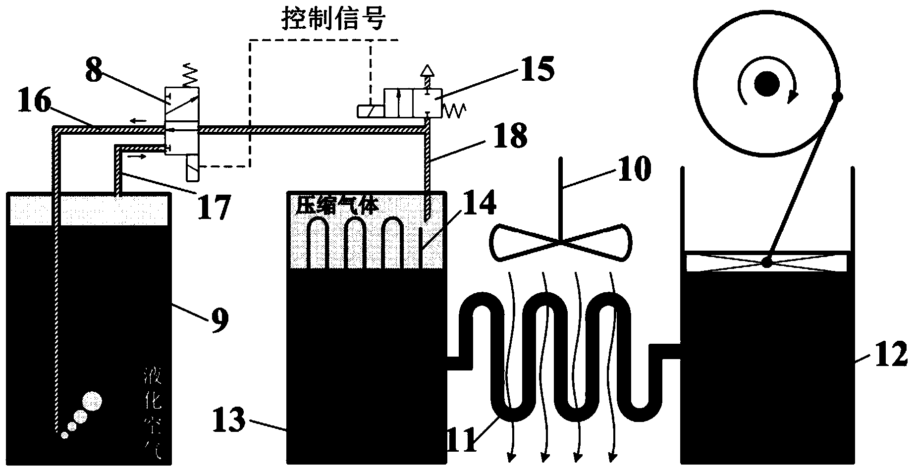
[0024] The whole system consists of a working tank (9), a heat exchange tank (13) and a piston cylinder (11). The pipeline (18) connected to the heat exchange tank (12) is divided into two branches, and two valves (8 ) is connected to the working tank (9), the other is connected to the two-position valve (15), and the injection pipe (16) connected to the two-position valve (8) is inserted into the working tank (9) once the liquid level, and connected to the two-position valve ( 8) The connected pipeline (17) is inserted above the liquid level in the working tank (9), the heat exchange tube (11) is connected in series between the heat exchange tank (13) and the piston cylinder (12), and the heat exchange tube (12) is placed outside The fan (10), the built-in heat exchanger (14) in the heat exchange tank (13) complete the gasification-compression process, expansion process and exhaust process.

[0025] Gasification-compression process: the two-position valve (8) is in the lower ...


PUM


Abstract

The invention relates to a method for achieving liquefied air cold recovery, belongs to the field of compressed air energy storage and utilization and mainly aims at providing a cold recovery method for vaporization heat absorption-compression heat release coupling and an achievement mode thereof for a liquefied air energy storage system. By means of the method, the cold utilization rate of liquefied air is improved, the heat-to-power conversion efficiency of the liquefied air can be remarkably improved, and the overall efficiency of the energy storage system is improved. A large amount of 'cold' is produced in the vaporization heat absorption process, and the cold serves as an important constituent part for liquefied air energy storage. The method is directly utilized in a mode that compressed air is directly in contact with the liquefied air, and an injection type structure is introduced on the basis of traditional thermodynamic cycle to form air-liquid two-phase heat exchange so as to improve the cold recycling rate.

Description

Technical field: [0001] The invention belongs to the field of compressed air energy storage and utilization, and relates to a thermal power conversion system of a liquefied air energy storage system. Background technique: [0002] The environmental pollution caused by the burning of fossil fuels is becoming more and more serious. The PM2.5 index exceeds the standard on a large scale, the annual number of smog days increases year by year, and carbon dioxide emissions continue to increase, all of which are inseparable from the burning of fossil fuels. [0003] Therefore, while the research on fossil fuel combustion technology continues to develop, the exploration of new energy technology is also greatly advancing. At present, countries are actively developing wind energy, nuclear energy, solar energy and other new energy sources. In my country, the use of new energy accounts for only 7% of the total energy, and it is expected to reach 15% by 2020. [0004] As an important p...

Claims


Application Information

Patent Timeline
Patent Type & Authority Applications(China)
IPC IPC(8): F01B29/10
Inventor 许未晴王佳张胜利蔡茂林
Owner BEIHANG UNIV
Learn More