Sagger automatic continuous charging device for electronic kiln

A charging device and kiln technology, which is applied to furnaces, furnace components, charge control, etc., can solve the problems of difficult assembly, damage to the screw and screw feeding pipe, and easy blockage, so as to ensure the effect of smooth movement. , avoid the waste of material escape, avoid the effect of dead angle phenomenon

Active Publication Date: 2014-11-26
SUZHOU HUIKE EQUIP CO LTD
View PDF8 Cites 4 Cited by
  • Summary
  • Abstract
  • Description
  • Claims
  • Application Information

AI Technical Summary

Problems solved by technology

However, most electronic powder materials do not need to be weighed before they are introduced into the furnace for firing, as long as the sagger is filled, so the weighing mechanism, weighing pan moving mechanism and metering frame in this patent scheme become It is superfluous, especially the automatic feeding mechanism recommended by this patent scheme has the following shortcomings: First, because it is a horizontal discharge, that is, the discharge port is located at the lower side of the end of the spiral feeding tube facing the weighing mechanism, so it is easy to appear due to the existence of a dead angle. The phenomenon of blockage; secondly, because the final power output shaft of the reduction box (equipped with a motor (the first motor in the patent)) used to drive the screw shaft to move is directly connected to the screw shaft, it is difficult to assemble on the one hand, and on the other hand On the one hand, when the motor drives the gear box to work, factors such as vibration, concentricity deviation between the final power output shaft of the gear box and the screw shaft will affect the movement effect of the screw shaft, and even the screw shaft on the screw shaft will appear. The scraping between the sheet and the inner wall of the screw feeding tube will damage the screw sheet and the screw feeding tube (caused by the change of the gap between the screw sheet and the inner wall of the screw feeding tube); thirdly, if the outlet is changed to (Transferred to) the end of the spiral feeding pipe, then there will be another problem that the material is difficult to accurately introduce into the sagger and cause material escape, because the centerline of the outlet is the same as the centerline of the spiral feeding pipe

Method used


Image

  • Sagger automatic continuous charging device for electronic kiln
  • Sagger automatic continuous charging device for electronic kiln

Examples


Embodiment Construction

[0020] In order to enable the examiners of the patent office, especially the public, to understand the technical essence and beneficial effects of the present invention more clearly, the applicant will describe in detail the following in the form of examples, but none of the descriptions to the examples is an explanation of the solutions of the present invention. Any equivalent transformation made according to the concept of the present invention which is merely formal but not substantive shall be regarded as the scope of the technical solution of the present invention.

[0021] In the following descriptions, all concepts involving up, down, left, right, front and rear directionality (or orientation) are for the position state of the picture being described, and the purpose is to facilitate the public Therefore, it cannot be understood as a special limitation on the technical solution provided by the present invention.

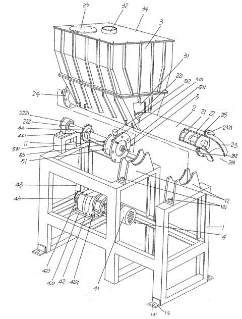
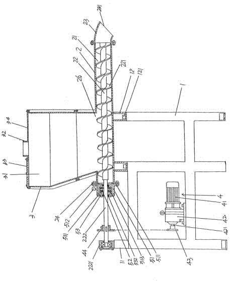
[0022] See figure 1 and figure 2 , shows a hollowed-o...


PUM


Abstract

The invention discloses a sagger automatic continuous charging device for an electronic kiln, and belongs to the technical field of electronic kiln auxiliary facilities. The sagger automatic continuous charging device comprises a rack, a spiral material conveying tube, a material storage box and a power transmission mechanism. The rack is supported on a terrace. The spiral material conveying tube is fixed on the top of the rack, a screw rod shaft is matched in a tube cavity of the spiral material conveying tube, and a spiral sheet is formed on the screw rod shaft. A closed end is formed at the left end of the spiral material conveying tube, and an opened end is formed at the right end of the spiral material conveying tube. The material storage box is fixedly connected with the top of the rack, and the bottom of a material storage box cavity is communicated with the tube cavity of the spiral material conveying tube. The power transmission mechanism is connected with the screw rod shaft. The sagger automatic continuous charging device for the electronic kiln is characterized in that the opened end of the spiral material conveying tube is connected with a bend connector in a matched mode, the bend connector is communicated with the tube cavity, a bend connector discharging opening of the bend connector faces downwards, the left end of the screw rod shaft stretches out of the tube cavity to form a screw rod shaft extension shaft section, the screw rod shaft extension shaft section is supported on the top of the rack, and the power transmission mechanism is connected with the screw rod shaft extension shaft section. Discharging smoothness is guaranteed, the spiral sheet can be prevented from scraping the inner wall of the tube cavity, and accordingly materials can be accurately led into a sagger.

Description

technical field [0001] The invention belongs to the technical field of supporting facilities for electronic kilns, in particular to an automatic continuous charging device for saggers used in electronic kilns, which is used for loading electronic powder materials into the saggers, and the saggers carry the electronic powder materials into the kiln Furnace fired. Background technique [0002] The electronic kiln mentioned above is used to burn electronic powder materials for electronic components, such as colored phosphors, lamp powders, barium titanate, yttrium trioxide, titanium dioxide, zirconia, alumina, Bismuth oxide, lead zirconate titanate, lithium iron phosphate or ferrite magnetic powder, etc. This kind of electronic powder material is not limited to the example, usually needs to be loaded into the sagger, and under the work of the continuous conveying device of the electronic kiln, the sagger is carried by the setter and introduced into the furnace from the input ...

Claims


Application Information

Patent Timeline
Patent Type & Authority Applications(China)
IPC IPC(8): F27D3/08
Inventor 陈斌张文俊
Owner SUZHOU HUIKE EQUIP CO LTD
Why Eureka
Try Eureka