A resistive deflection measuring device

A deflection measurement, resistive technology, applied in the field of deflection measurement, can solve the problems of insufficient accuracy and stability, difficult to meet accuracy and linearity, and difficult to meet the accuracy requirements, and to achieve a wide range of applications, high accuracy and simple structure. Effect

Active Publication Date: 2017-01-04
HOHAI UNIV
View PDF8 Cites 0 Cited by
  • Summary
  • Abstract
  • Description
  • Claims
  • Application Information

AI Technical Summary

Problems solved by technology

However, in the current use process, the device using this method also has certain shortcomings. For example, some patents use a ruler installed on a straight pipe for manual reading. This kind of instrument has low precision.
As for the photoelectric sensor for reading, due to the influence of water surface tension and no amplification function, its accuracy and stability are also not good enough
In addition, there is a patent for measuring deflection, which uses a micro-pressure sensor or a pressure transmitter to measure the pressure of the water column, because the change in the pressure of the water column is extremely small, and the water pressure of the connector is smaller after the partial pressure of multiple tubes, so it is also difficult Meet ideal precision requirements
There is also the conversion of liquid level displacement by buoyancy or float, and the buoyancy change or float displacement is sensed by elastic elements or photoelectric sensors. This method has problems such as secondary conversion, friction and verticality of the float, so its accuracy and linearity are difficult to meet. Existing Application Requirements

Method used


Image

  • A resistive deflection measuring device
  • A resistive deflection measuring device
  • A resistive deflection measuring device

Examples


Embodiment 1

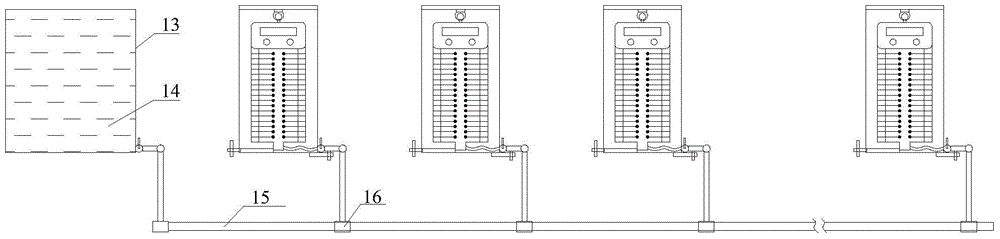
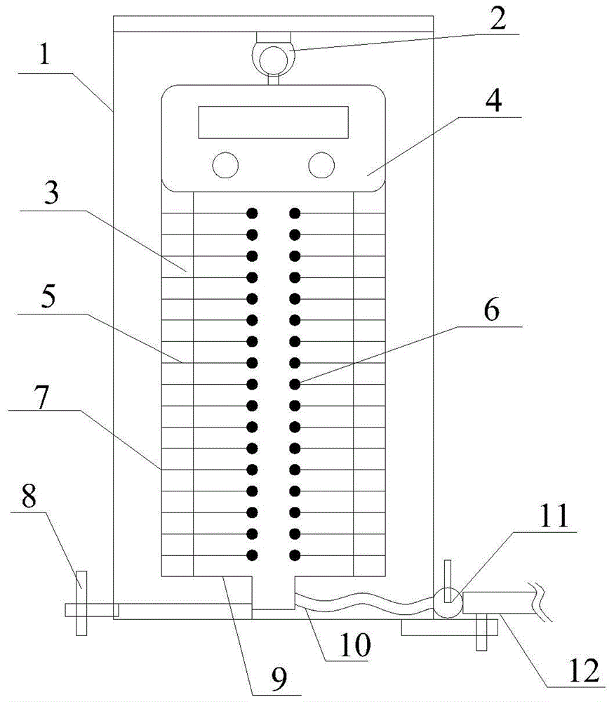
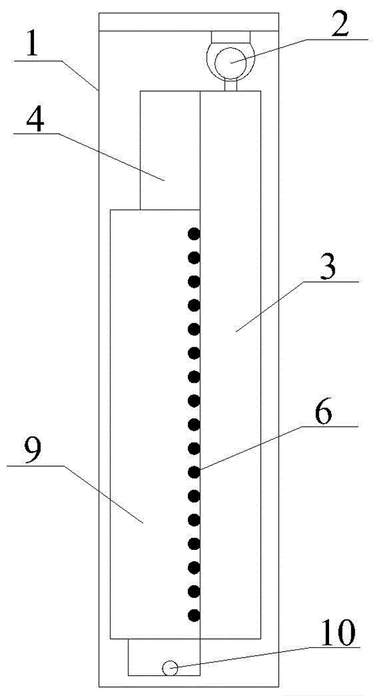
[0038] see figure 1 , figure 2 , image 3 , Figure 4 , Figure 5 As shown, the resistive deflection measuring device of the present invention comprises a transparent outer frame (1), a hinged ball (2), a circuit board (3), a wireless transceiver (4), an insulation resistance needle (5), a conductive resistance head ( 6), resistance rod (7), leveling screw (8), semi-cylindrical transparent standpipe (9), flexible pipe (10), valve joint (11) and connecting capillary (12).

[0039] Such as figure 2As shown, the semi-cylindrical transparent standpipe (9) is located in the transparent outer frame (1), and the resistance rod (7), the insulation resistance needle (5) and the conductive resistance head (6) are customized on the circuit board (3). The cylindrical transparent standpipe (9) and the wireless transceiver device (4) are fixedly clamped on the circuit board (3), the circuit board (3) has a certain thickness, and its upper end is connected with the transparent outer f...


PUM


Abstract

The invention discloses a resistive deflection measuring device, which comprises a transparent outer frame, a hinge ball, a circuit board, a wireless transceiver device, an insulating resistance needle, a conductive resistance head, a resistance rod, a leveling screw, and a semi-cylindrical transparent standpipe , hoses, valve fittings and connecting tubing. The semi-cylindrical transparent standpipe is located in the outer frame, the resistance rod, the insulation resistance needle and the conductive resistance head are customized on the circuit board, and the transparent standpipe and the wireless transmitting device are fixed on the circuit board. The method is to measure the current change caused by the change of the electrolyte height in the standpipe, and obtain the deflection value according to the relationship between the current change and the structural deflection value. The invention integrates the connecting pipe and the resistance method measurement technology, can be applied to bridge engineering, and can also be widely used in vertical displacement and deflection measurement in other projects such as buildings and foundation pits, and is convenient to use; due to the high accuracy of current measurement , therefore, the measuring device improves the accuracy of deflection measurement.

Description

technical field [0001] The invention belongs to the field of deflection measurement, in particular to a resistance type deflection measurement device. Background technique [0002] At present, an important content in bridge load test and bridge construction jacking process is the measurement of deflection. At present, the deflection tests are mainly divided into the following categories: [0003] 1. Level or total station. The principle is to pre-arrange a number of fixed measuring points on the structure, place one point on a certain fixed point or a relatively fixed point, and then use the level to read the height of each tower foot after each loading according to the principle of leveling. Elevation, the deflection at this place can be obtained after subtracting the front and back. The advantage is that it can carry out multi-point measurement, no need to install a base or bracket, and the amount of equipment to be carried is small. The disadvantage is that the measur...

Claims


Application Information

Patent Timeline
Patent Type & Authority Patents(China)
IPC IPC(8): G01B7/16G01M5/00
Inventor 陈欣赵月悦吉伯海傅中秋
Owner HOHAI UNIV
Why Eureka
Try Eureka