
Base station clock synchronization method in communication network

A communication network and clock synchronization technology, which is applied in the direction of synchronization devices, wireless communications, electrical components, etc., can solve the problems of increasing product costs and inability to achieve synchronization, and achieve manufacturing cost savings, real-time measurement and compensation processes, and flexible networking methods Effect

Inactive Publication Date: 2014-11-26
BEIJING XINWEI TELECOM TECH
View PDF6 Cites 15 Cited by
  • Summary
  • Abstract
  • Description
  • Claims
  • Application Information

AI Technical Summary

Problems solved by technology

However, this method has the following defects: on the one hand, each base station needs to install a GPS receiving module, which virtually increases the product cost; on the other hand, for some special tunnel communication occasions (such as mine communication), due to GPS Receiver and / or GPS signal unavailable, resulting in no synchronization between all base stations

Method used


Image

  • Base station clock synchronization method in communication network
  • Base station clock synchronization method in communication network
  • Base station clock synchronization method in communication network

Examples


Embodiment Construction

[0018] The specific embodiment of the present invention will be described in detail below in conjunction with the accompanying drawings.

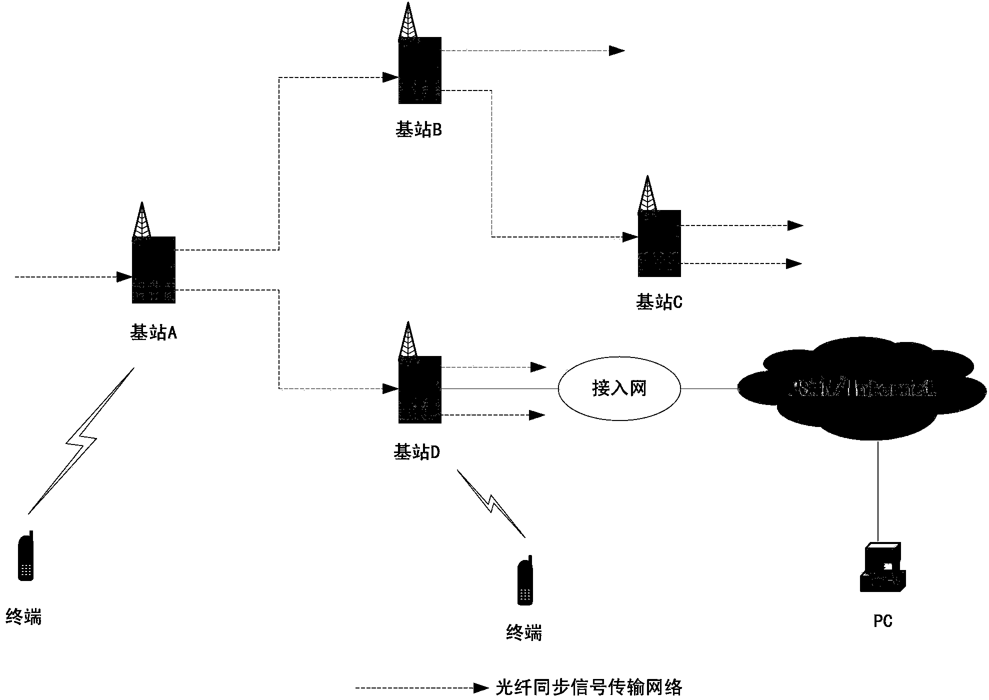
[0019] There are 4 base stations A, B, C, and D in the communication network of this embodiment. These base stations do not need to install GPS receiving modules in the base stations, but by laying optical fiber synchronous transmission networks between different base stations, the communication between the base stations can be easily realized. Clock synchronization. Each base station has 1 optical fiber interface for connecting with its master synchronous base station, and 2 optical fiber interfaces for connecting with its own slave synchronous base station, and can be connected with other 3 base stations arbitrarily. Each base station is equipped with 1 slave synchronization signal processing module, 2 master synchronization signal processing modules and 1 adaptive delay measurement and compensation module. The slave synchronization signa...


PUM


Abstract

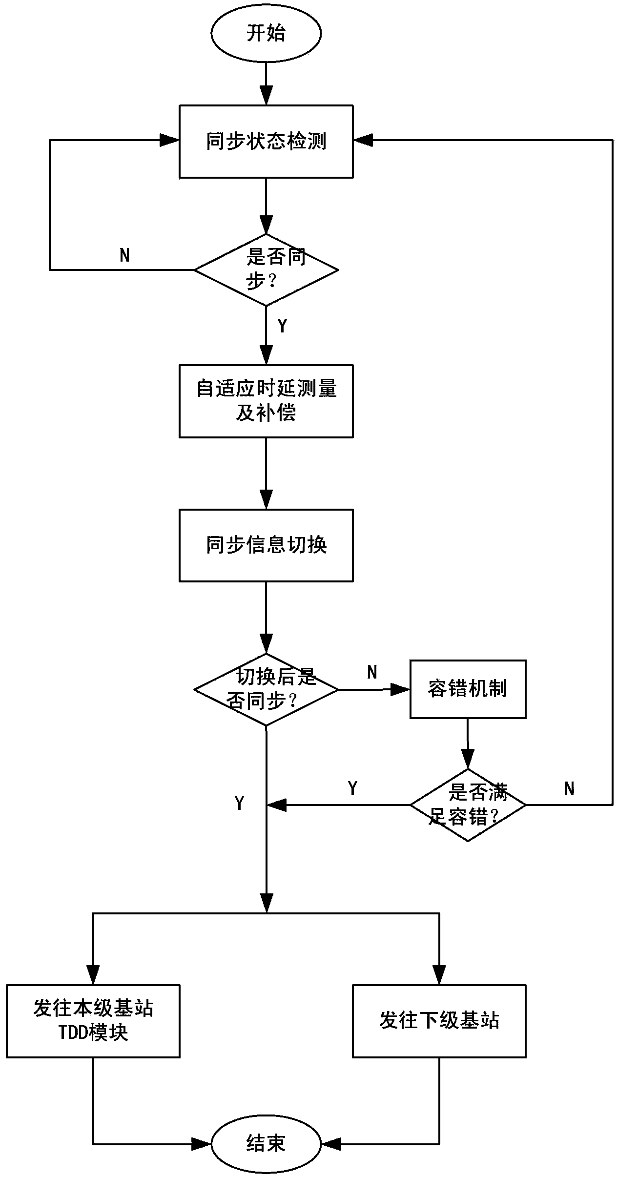
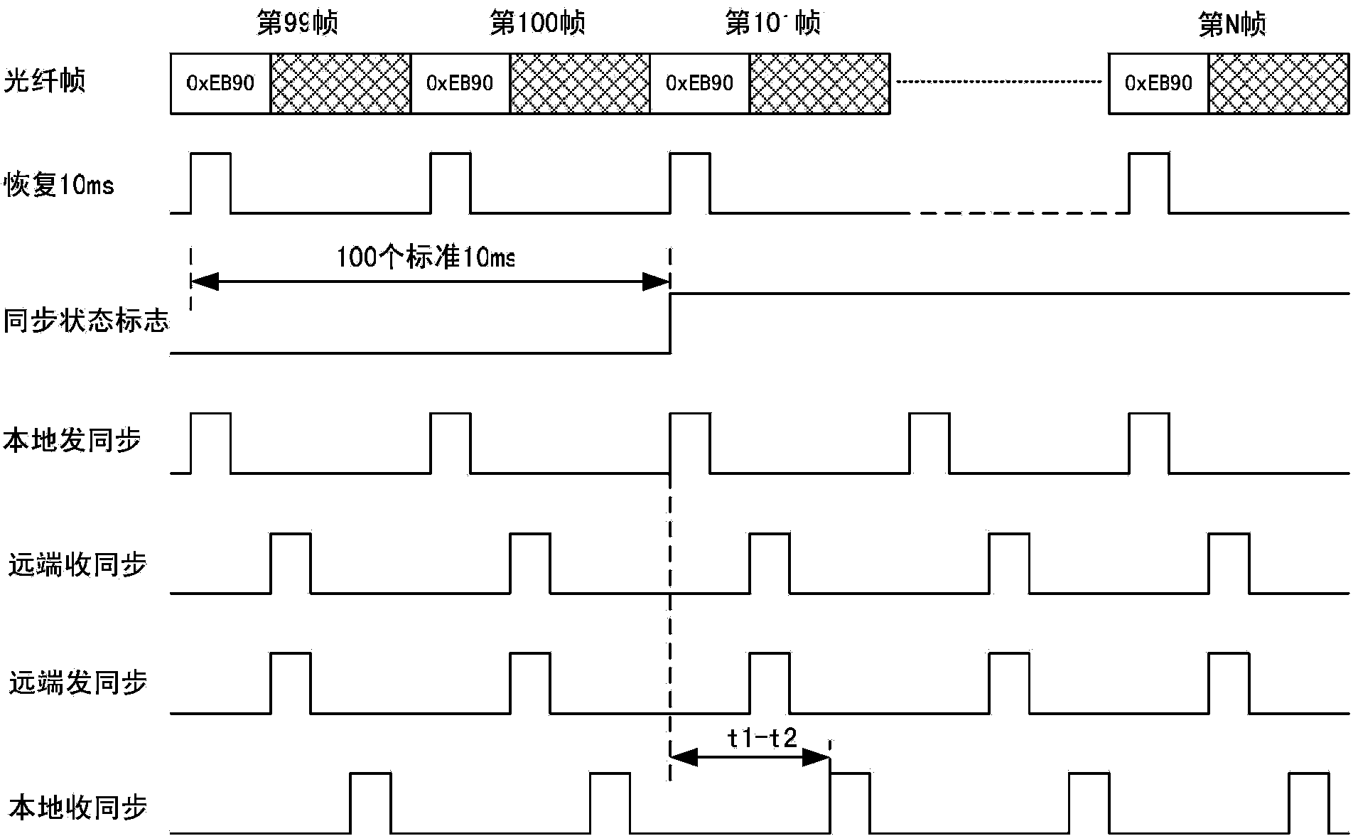
The invention brings forward a base station clock synchronization method. Any base station in a network has an optical fiber interface connected with a main synchronous base station of the base station itself and a plurality of optical interfaces connected with a slave synchronous base station of the base station itself. A certain base station is selected as a source base station and any other base stations are connected to the source station directly or in a cascading mode; and synchronization of any pair of main and slave base stations is as follows: a, an initial synchronization state of a slave base station is set as an out-of-step state and a main base station sends a local synchronization signal; b, the slave base station receives the signal and then carries out synchronization detection; and of the detection is successful, the synchronization state entrance is carried out; c, once the main base station knows that the slave base station enters the synchronization state, the main base station measures transmission delay time between the main base station and the slave base station; and after measurement is completed, the local synchronization signal is sent to the slave base station with time ahead of the transmission delay time and the slave base station switches the local synchronization signal into a received synchronization signal; and d, the slave base station carries out synchronization state detection all the time; and if the detection is not successful, out-of-step state entrance is carried out and returning to the step b is carried out.

Description

technical field [0001] The invention relates to the field of wireless communication, in particular to a method for clock synchronization of base stations in a communication network. Background technique [0002] For Time Division Multiple Access (TDMA) mobile communication systems, in order to achieve clock synchronization between base stations, one way is to use the Global Positioning System (GPS) synchronization method. Each base station in the system uses GPS as a reference to achieve Clock synchronization between base stations. However, this method has the following defects: on the one hand, each base station needs to install a GPS receiving module, which virtually increases the product cost; on the other hand, for some special tunnel communication occasions (such as mine communication), due to GPS Receiver and\or GPS signal unavailable, resulting in no synchronization between all base stations. [0003] Therefore, in order to solve the problem of base station clock sy...

Claims


Application Information

Patent Timeline
IPC IPC(8): H04W56/00
Inventor 王盖贾俊明张宝功李金安
Owner BEIJING XINWEI TELECOM TECH
Learn More