Blood pressure meter

A sphygmomanometer and blood pressure technology, which is applied in the field of sphygmomanometers, can solve problems such as miniaturization and thinning of sphygmomanometers, and achieve the effects of reducing assembly workload, product cost, and number of components

Active Publication Date: 2014-11-26
OMRON HEALTHCARE CO LTD
View PDF8 Cites 5 Cited by
  • Summary
  • Abstract
  • Description
  • Claims
  • Application Information

AI Technical Summary

Problems solved by technology

Therefore, space is required for arranging air piping and air passages, and there is a problem that it is difficult to reduce the size and thickness of the sphygmomanometer

Method used


Image

  • Blood pressure meter
  • Blood pressure meter
  • Blood pressure meter

Examples


Embodiment Construction

[0043] Embodiments of the present invention will be described in detail below with reference to the drawings.

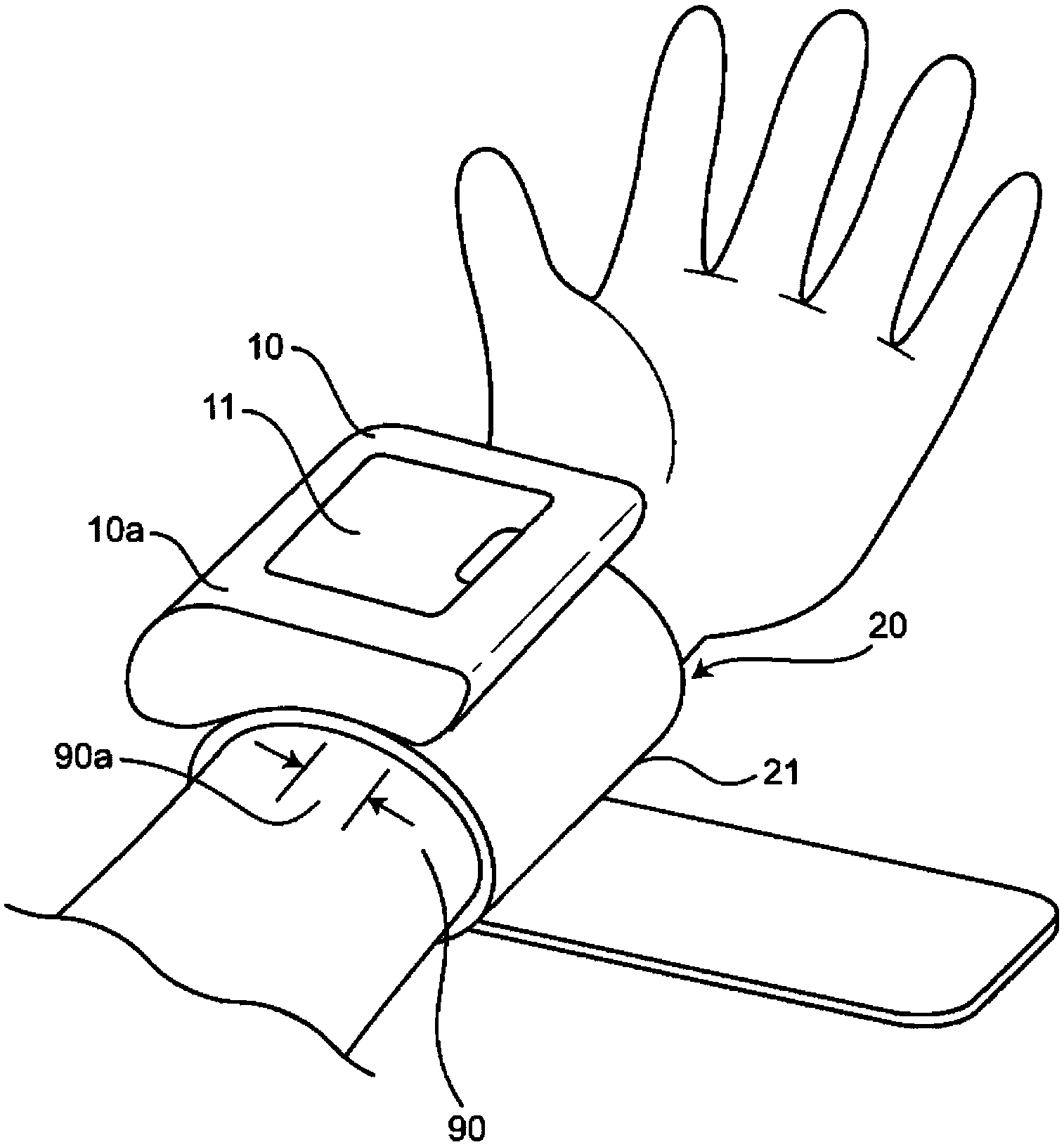
[0044] figure 1 The appearance of the sphygmomanometer in a state in which the sphygmomanometer of the present invention is wound and mounted on the left wrist 90 of a subject is shown in a perspective view.

[0045] like figure 1 As shown, the sphygmomanometer of this embodiment includes: a cuff (cuff) 20 serving as a blood pressure measurement cuff; and a main body 10 attached to face the cuff 20 . In addition, the blood pressure monitor has a display unit 11 arranged along the outer surface 10 a of the main body 10 on the side opposite to the cuff 20 .

[0046] The main body 10 has a substantially rectangular shape when viewed from a direction perpendicular to the outer surface 10a. figure 1 Among them, the longitudinal direction (left-right direction) of the main body 10 is substantially parallel to the upper part of the outer peripheral surface of the cuff 20...


PUM


Abstract

This blood pressure meter is configured in such a manner that a pump unit (31) is connected to a fluid bag (22) through a first fluid path (301). The first fluid path (301) extends straight in the Z-direction between the pump unit (31) and the fluid bag (22) and is adapted so as to deliver air, which is supplied from the pump unit (31), into the fluid bag (22) or so as to deliver air, which is within the fluid bag (22), to a valve.

Description

technical field [0001] The present invention relates to a sphygmomanometer comprising a cuff for blood pressure measurement that compresses a site to be measured, and a main body attached to the cuff. Background technique [0002] Conventionally, such a sphygmomanometer is known in which, for example, a DC motor-driven rotary pump is housed in a case, and air is supplied to a cuff from an air outlet of the rotary pump through an air pipe. [0003] In addition, as disclosed in Patent Document 1 (Japanese Patent Laid-Open Publication No. 2010-88513), a known sphygmomanometer has an inner case housed inside the sphygmomanometer case, and an air circuit component is fitted into the inner case. , the air circuit part is connected to the air channel formed on the inner shell to supply air to the cuff. [0004] Patent Document 1: Japanese Patent Laid-Open Publication No. 2010-88513 [0005] In the conventional blood pressure monitor described above, the air piping and the air pas...

Claims


Application Information

Patent Timeline
Patent Type & Authority Applications(China)
IPC IPC(8): A61B5/022
CPCA61B2562/16A61B2560/0412A61B2562/225A61B5/022A61B5/0225A61B5/02233
Inventor 西冈孝哲山下新吾柳瀬真孝上坂知里土井龙介有贺裕恭池田惠太八丸泉
Owner OMRON HEALTHCARE CO LTD
Why Eureka
Try Eureka