Annular combustion chamber bypass
A technology of annular combustion chamber and burner, which is applied in the direction of combustion chamber, continuous combustion chamber, combustion method, etc., can solve problems such as the limitation of the available partial load range of gas turbines, and achieve simple assembly and disassembly, simple realization, and emission reduction. Effect
- Summary
- Abstract
- Description
- Claims
- Application Information
AI Technical Summary
Problems solved by technology
Method used
Image

Examples
Embodiment Construction
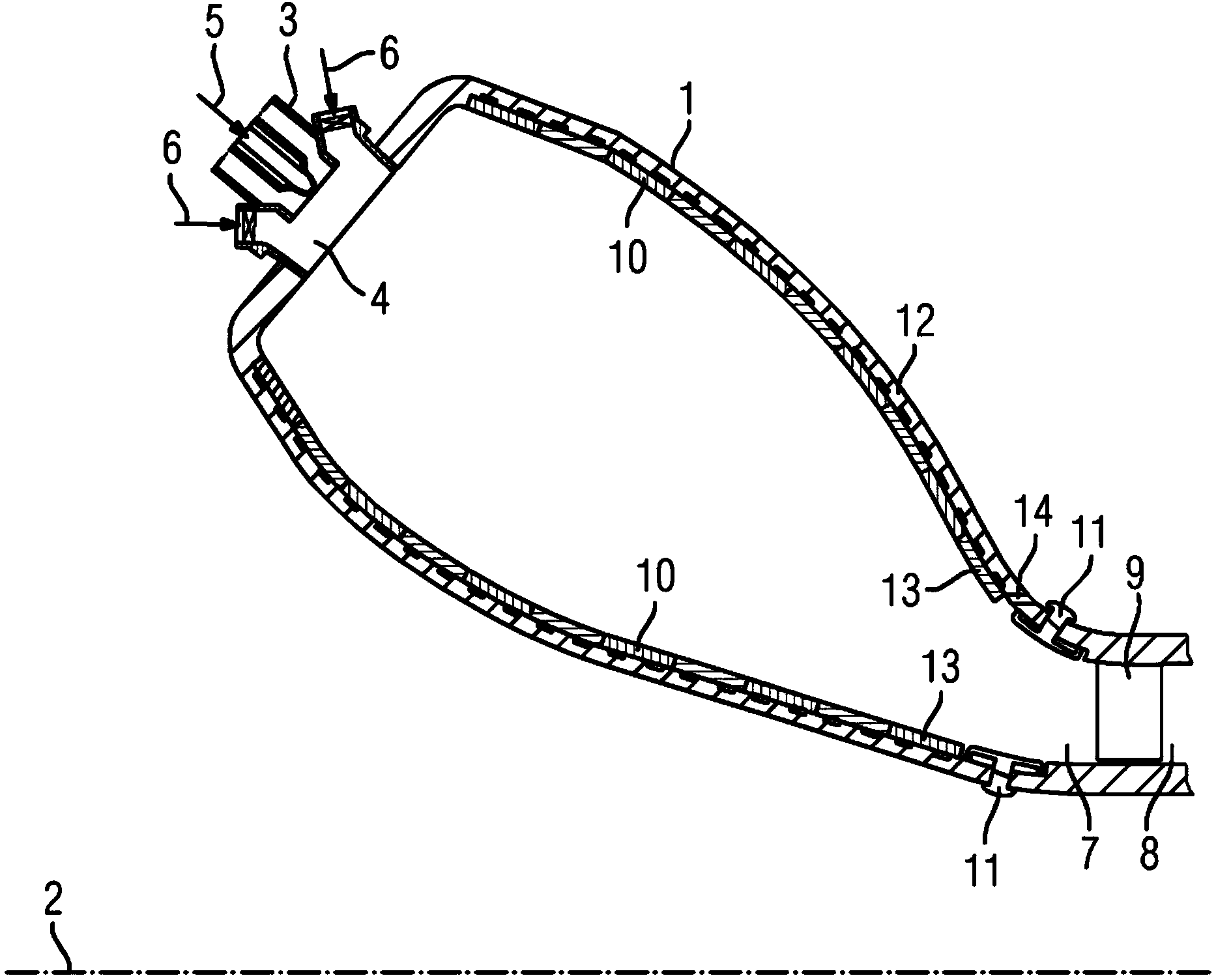
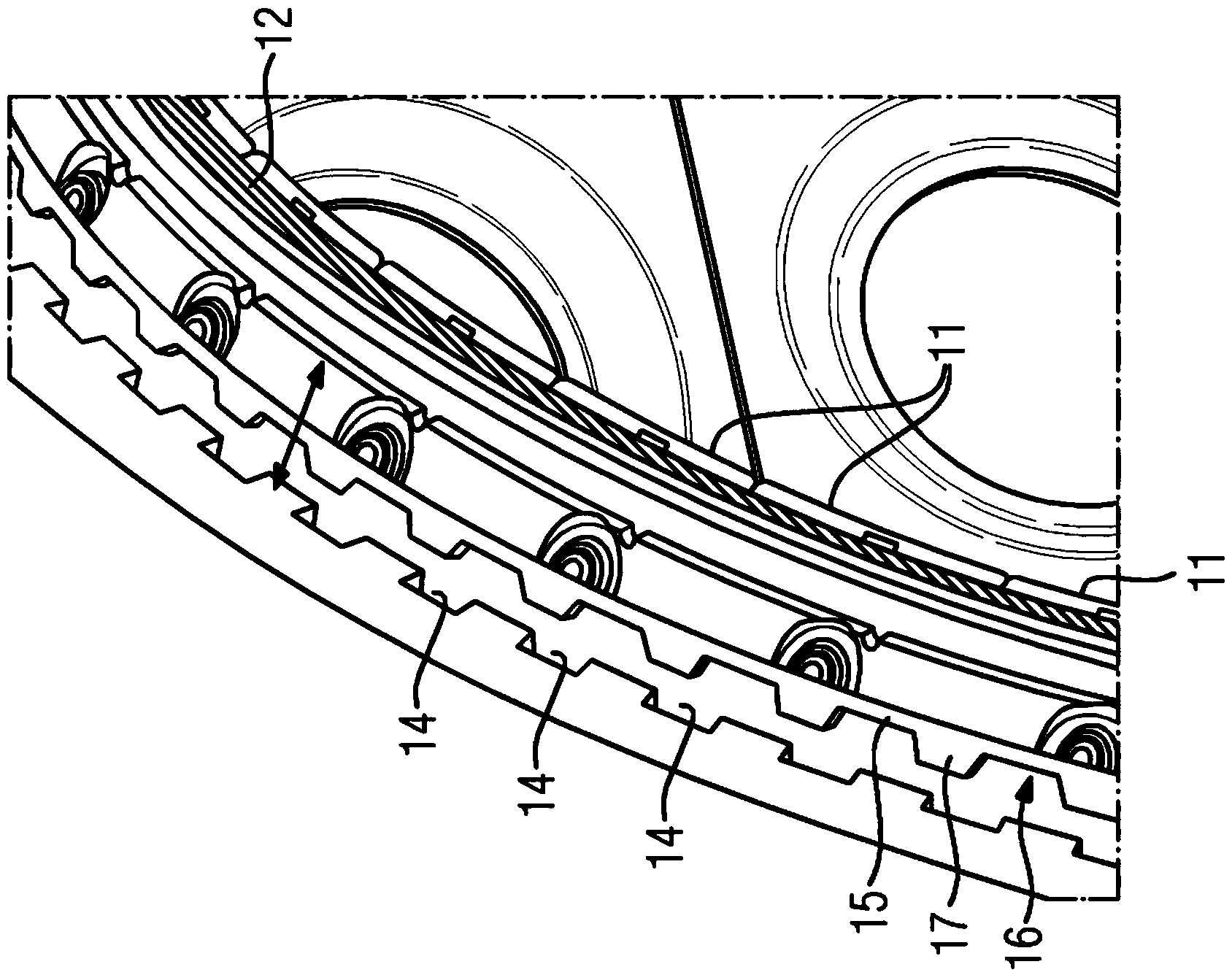
[0023] figure 1 The combustion system of the annular combustion chamber 1 according to the invention is shown schematically and exemplarily. The annular combustion chamber 1 consists of a closed ring arranged around the axis of rotation 2. The burner 3 is arranged in the inlet 4 in the upper region of the combustion chamber 1. There, fuel 5 is mixed with compressed air 6. The self-combustion is realized in the combustion chamber 1. The hot combustion gas enters the turbine cavity 8 through the outlet 7 where the combustion gas contacts the first blade 9. In order to protect before ignition, the annular combustion chamber 1 is lined with a ceramic heat shield 10 and a metal heat shield 11, which are fixed on the shell 12.
[0024] According to the present invention, the combustion chamber shell 12 is provided with a channel in the area of the outlet 7 between the last ceramic heat shield column 13 (ie the penultimate column heat shield) and the metal inlet shell plate (ie the...
PUM
 Abstract
Description
Claims
Application Information
 - Generate Ideas
- Intellectual Property
- Life Sciences
- Materials
- Tech Scout
- Unparalleled Data Quality
- Higher Quality Content
- 60% Fewer Hallucinations
Browse by: Latest US Patents, China's latest patents, Technical Efficacy Thesaurus, Application Domain, Technology Topic, Popular Technical Reports.
© 2025 PatSnap. All rights reserved.Legal|Privacy policy|Modern Slavery Act Transparency Statement|Sitemap|About US| Contact US: help@patsnap.com