
An automatic chamfering machine and its control method

A chamfering machine and chamfering technology, applied in the mechanical field, can solve the problems of high labor intensity, long time-consuming, high risk factor, etc., and achieve the effects of reducing labor intensity, stable operation, and improving work efficiency

Active Publication Date: 2017-06-06
SHENZHEN XIANGTONG PHOTOELECTRIC TECH
View PDF8 Cites 0 Cited by
  • Summary
  • Abstract
  • Description
  • Claims
  • Application Information

AI Technical Summary

Problems solved by technology

The existing technology requires manual operation, which is labor-intensive, inefficient, time-consuming, and has a high risk factor

Method used


Image

  • An automatic chamfering machine and its control method
  • An automatic chamfering machine and its control method
  • An automatic chamfering machine and its control method

Examples


Embodiment Construction

[0027] The present invention provides an automatic chamfering machine and its control method. In order to make the purpose, technical solution and effect of the present invention clearer and clearer, the present invention will be further described in detail below with reference to the accompanying drawings and examples. It should be understood that the specific embodiments described here are only used to explain the present invention, not to limit the present invention.

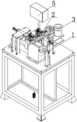
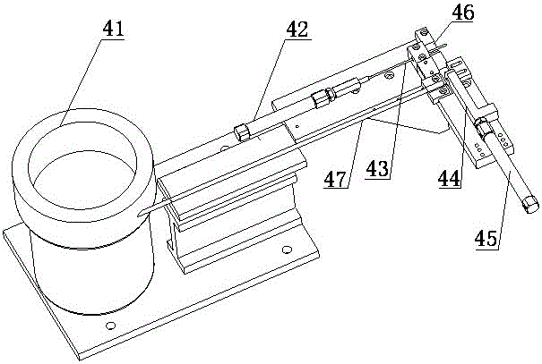
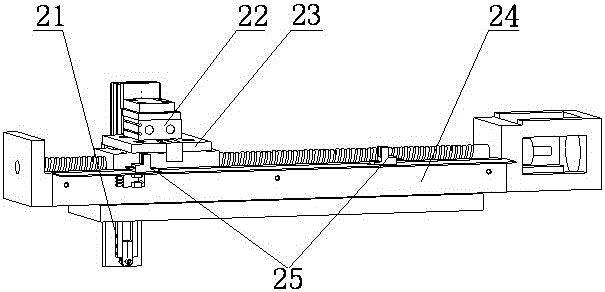
[0028] Such as figure 1 with figure 2 As shown, a kind of automatic chamfering machine comprises frame 7, is arranged on the frame 7 and is used for material conveying system 4 in the chamfering machine, is connected with material conveying system 4 and is used for material conveying system 4 The chamfering identification system 3 for identifying the chamfering end of the conveyed material, the feeding system 2 connected with the chamfering identification system 3 for transferring the identified chamfered e...


PUM


Abstract

The invention discloses an automatic chamfering machine and a control method thereof. The automatic chamfering machine structurally comprises a rack, a material conveying system, a chamfering identifying system, a feeding system and a chamfering system, wherein the material conveying system is arranged on the rack and used for conveying a material into a chamfering machine body; the chamfering identifying system is connected with the material conveying system and used for identifying one end, which is to be chamfered, of the material conveyed by the material conveying system; the feeding system is connected with the chamfering identifying system and used for transferring the material with the to-be-chamfered end identified; the chamfering system is connected with the feeding system and used for chamfering the to-be-chamfered end of the material. With the adoption of the automatic chamfering machine and the control method thereof, switching from chamfering semi-automation to chamfering full-automation is realized, the labor intensity of operators is reduced, and the working efficiency is improved.

Description

technical field [0001] The invention relates to the mechanical field, in particular to an automatic chamfering machine and a control method thereof. Background technique [0002] At present, the chamfering process of the SC front cover is mostly completed by a single station and a single person. The operator manually puts the front cover into the spindle chuck, and manually pulls the clamping system with the left hand to clamp the front cover, and then starts the spindle. With the motor, the right hand pulls the tool table to move to chamfer the section of the front cover. After the chamfering process is completed, the tool table needs to be reset and the spindle clamping system is released to make the front cover fall down, completing a process cycle. The prior art requires manual operation, which has high labor intensity, low efficiency, long time consumption and high risk factor. [0003] Therefore, the prior art still needs to be improved and developed. Contents of th...

Claims


Application Information

Patent Timeline
Patent Type & Authority Patents(China)
IPC IPC(8): B23D79/00B23Q7/00
Inventor 王光辉
Owner SHENZHEN XIANGTONG PHOTOELECTRIC TECH
Learn More