Self-locking booster compliant end gripper for tandem living hinges

A technology of loose-leaf hinges and grippers, which is applied in the direction of manipulators, program-controlled manipulators, chucks, etc., can solve the problems of insufficient driving force, insufficient pressure, and large force ratio, and achieve reliable grasping and good force-increasing effects , good versatility

Active Publication Date: 2016-08-10
泰州市华驰不锈钢制品有限公司
View PDF5 Cites 0 Cited by
  • Summary
  • Abstract
  • Description
  • Claims
  • Application Information

AI Technical Summary

Problems solved by technology

Before the present invention, the patent application (a multi-joint flexible manipulator, 200810023616.5) proposed a rubber bellows expansion-loaded pneumatic artificial muscle driver, a flexible bending joint of the hinge skeleton, and its disadvantages are: ① rubber bellows pneumatic The inner chamber pressure of the artificial muscle driver is not strong enough, and the driving force is not strong enough; ②Return to the initial straight state by the action of the torsion spring; ③The direction of the driving force acting on the loose-leaf hinge skeleton cannot be adjusted, and the versatility of grasping objects is not good enough; ④The stress state of the loose-leaf hinge is not good, and a considerable part of the output force of the artificial muscle acts on the torsion spring to deform it, thereby reducing the grasping force output by the flexible joint. The larger the proportion of spring deformation force is; ⑤Especially driven by artificial muscles, with the larger the angular displacement of the hinge, the greater the pressure increment of the inner chamber of the artificial muscle required for the unit increment of angular displacement, the higher the hinge will be. Difficult to bend, that is, the slope of the angular displacement-air pressure curve of the flexible finger hinge is getting smaller and smaller

Method used


Image

  • Self-locking booster compliant end gripper for tandem living hinges
  • Self-locking booster compliant end gripper for tandem living hinges
  • Self-locking booster compliant end gripper for tandem living hinges

Examples


Embodiment Construction

[0023] Below is working principle and working process of the present invention:

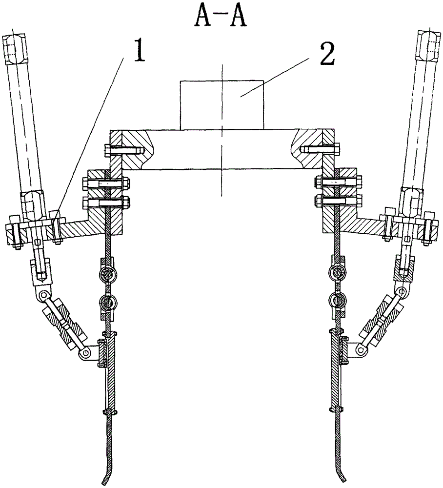
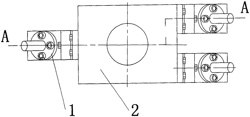
[0024] Such as figure 1 , 2 As shown, the research and analysis process: For long and rectangular complex objects, after theoretical analysis and experimental research, according to the range of shape, size and material of the grasped object, the safe range of grasping contact force is determined, and the design is optimized. Structural dimensions, two leaf spring characteristic parameters and pre-tightening angle determine the size of the palm, and adjust the length of the two power levers (left threaded hinge lever 11a, threaded sleeve 12a, right threaded hinge lever 13a form).

[0025] The optimization goal is: when the required grasping contact force is reached, the air pressure in the inner guide cylinder 1a reaches the system pressure, and the final included angle exceeds the friction angle of the linear guide slider 8a on the linear guide chute 7a, resulting in self-locking, and the inner...


PUM


Abstract

The invention relates to a self-locking power-increasing type compliant end gripper of loose-leaf hinges in series. The end gripper consists of a palm and three flexible fingers. The palm has two structures: rectangular and hexagonal; each flexible finger has the same structure. It is mainly composed of an inner guide cylinder, a linear guide rail (or linear bearing) and a series loose-leaf hinge; a torsion spring is installed on each hinge mandrel of the series loose-leaf hinge, and the characteristic parameters and pre-tightening angle of the torsion spring are determined according to the captured It is optimized and designed based on the characteristics of the object; it is driven by the cylinder to generate the gripping force. This end gripper is applied to the gripping of fragile and brittle objects, or special-shaped objects with changing shapes and sizes. It belongs to the application technology of robotics and mechatronics. field; connected with the robot body, it is especially suitable for the production and logistics fields of food, agricultural products, light industrial products, such as grabbing, sorting and packaging.

Description

Technical field: [0001] The invention relates to a self-locking power-increasing type compliant end gripper of loose-leaf hinges in series. The end gripper consists of a palm and three flexible fingers. The palm has two structures: rectangular and hexagonal; each flexible finger has the same structure. It is mainly composed of an inner guide cylinder, a linear guide rail (or linear bearing) and a series loose-leaf hinge; a torsion spring is installed on each hinge mandrel of the series loose-leaf hinge, and the characteristic parameters and pre-tightening angle of the torsion spring are determined according to the captured It is optimized and designed based on the characteristics of the object; it is driven by the cylinder to generate the gripping force. This end gripper is applied to the gripping of fragile and brittle objects, or special-shaped objects with changing shapes and sizes. It belongs to the application technology of robotics and mechatronics. field; connected with...

Claims


Application Information

Patent Timeline
Patent Type & Authority Patents(China)
IPC IPC(8): B25J15/12B25J15/10B25J9/14
Inventor 章军王芳朱飞成张秋菊
Owner 泰州市华驰不锈钢制品有限公司
Why Eureka
Try Eureka