Deformable wing device and airplane applying same

A wing and aircraft technology, applied in the field of deformable wing devices, can solve the problems that the design method cannot meet the requirements, the wing has a large adjustment range, and cannot have external wings, etc., so as to improve the maneuverability of the aircraft and improve the control. The effect of safety performance and high rigidity

Active Publication Date: 2014-12-03
HARBIN INST OF TECH SHENZHEN GRADUATE SCHOOL
View PDF8 Cites 5 Cited by
  • Summary
  • Abstract
  • Description
  • Claims
  • Application Information

AI Technical Summary

Problems solved by technology

In addition, with the development of submarines and unmanned aerial vehicles, military powers are conducting research on a new unmanned aerial vehicle technology - unmanned aerial vehicles are loaded into the launch box of submarines and sent directly to the air to perform tasks, so unmanned aerial vehicles are During the launch process, there is no need to have external

Method used


Image

  • Deformable wing device and airplane applying same
  • Deformable wing device and airplane applying same
  • Deformable wing device and airplane applying same

Examples


Embodiment 1

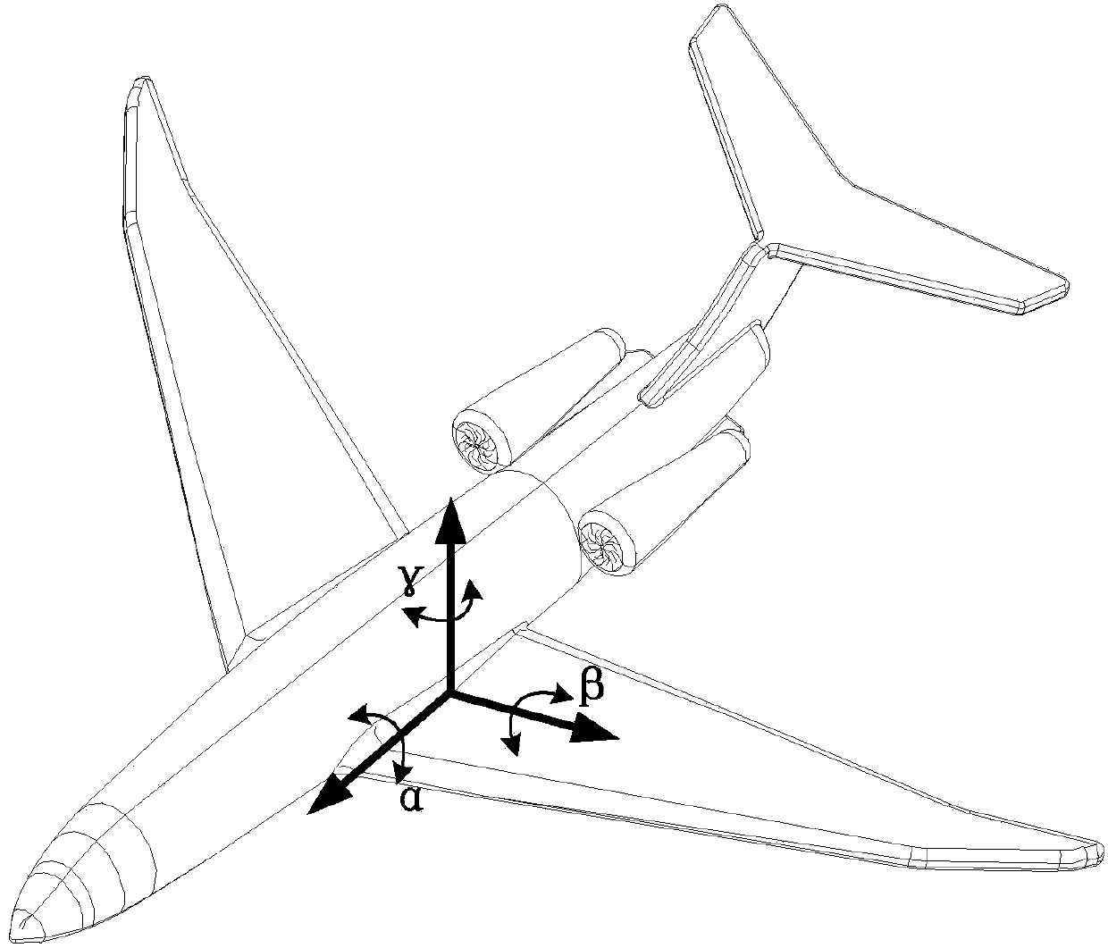
[0029] Such as figure 2 As shown, the aircraft of the present embodiment comprises: a nose 1, a tail 9, and a deformable wing device.

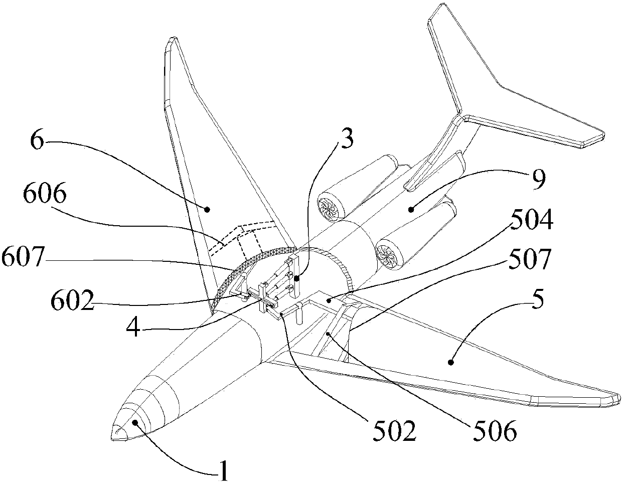
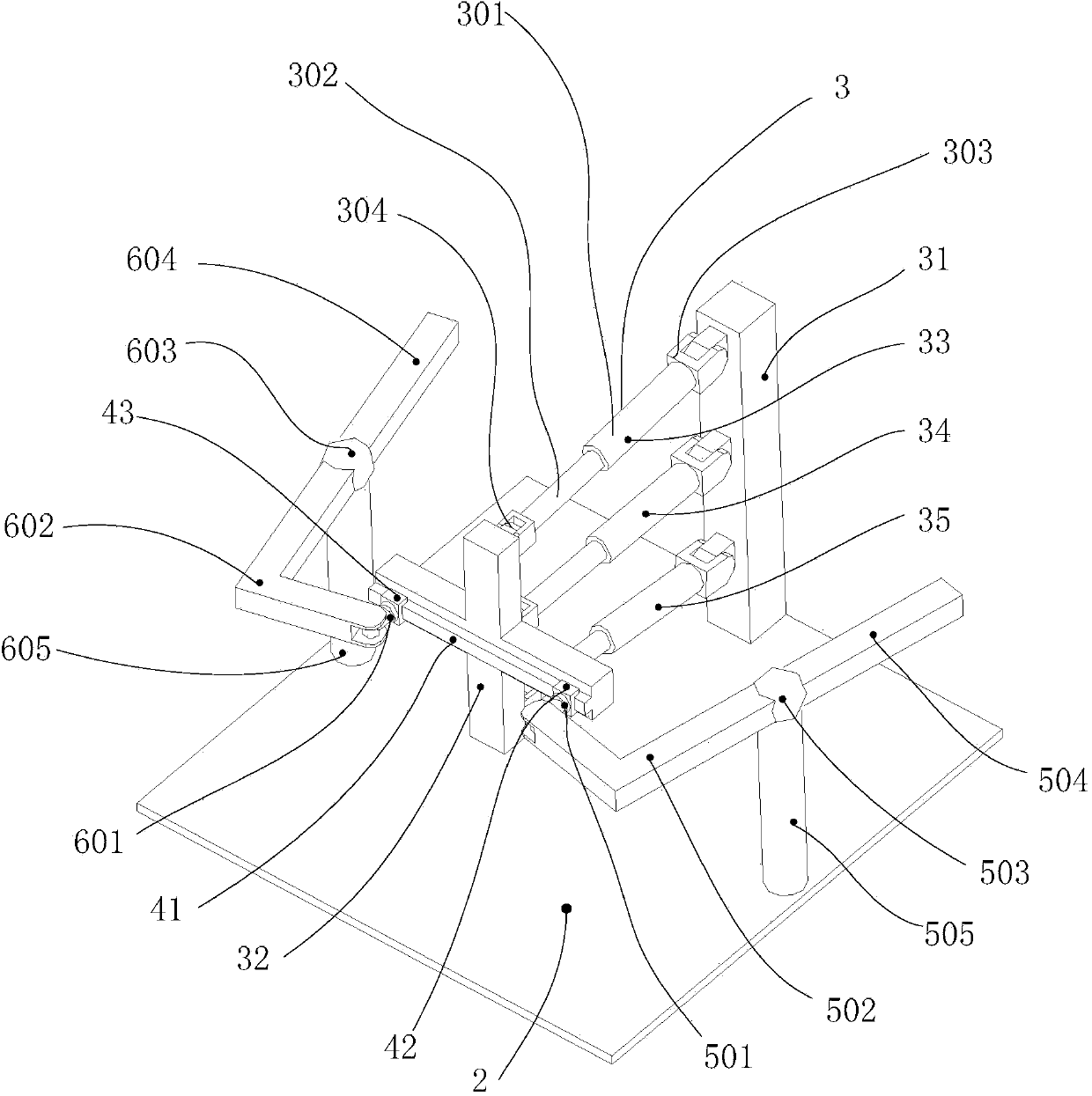
[0030] Such as image 3 As shown, the deformable wing device includes: a fuselage central platform 2 , a parallel drive mechanism 3 , a transmission connection mechanism 4 , a left wing mechanism 5 , and a right wing mechanism 6 . The central fuselage platform 2 is located within the aircraft.

[0031] The parallel driving mechanism 3 is installed in the middle of the central platform 2 of the fuselage, and the plane where the three driving branches are located is kept perpendicular to the upper surface of the central platform 2 of the fuselage, and the direction of the three driving branches is the direction of the nose 1 and the tail 9. The direction of the center line. The parallel driving mechanism 3 is a 3RPR parallel driving mechanism, which includes a fixed platform 31, a moving platform 32, and three driving branches connecting the...


PUM


Abstract

The invention provides a deformable wing device which comprises a fuselage central platform, a parallel driving mechanism, a transmission connecting mechanism, a left wing mechanism and a right wing mechanism, wherein the parallel driving mechanism comprises a fixed platform, a movable platform, and three driving branches connected with the fixed platform and the movable platform; the fixed platform is fixed on the fuselage central platform; the three driving branches share the same plane and are not parallel in pairs; each driving branch comprises two connecting rods which share the same line, one ends of the two connecting rods are respectively connected with the fixed platform and the movable platform by a revolute pair, and the other ends of the two connecting rods are connected with each other by a sliding pair; the transmission connecting mechanism comprises a linear guide rail, and a left sliding block and a right sliding block which are capable of sliding on the linear guide rail; the linear guide rail is fixedly connected with the movable platform; the left wing mechanism and the right wing mechanism respectively comprise a universal joint, an L-shaped transmission beam, a ball pair, a main beam and a support pillar; the short arm end of each L-shaped transmission beam is connected with the corresponding universal joint, and the universal joint is fixed on the sliding block arranged at the corresponding side; the long arm end of each L-shaped transmission beam and one end of each main beam are respectively fixedly connected with the corresponding ball pair, and the main beams and the long arms of the L-shaped transmission beams share the same line; the ball pairs are movably connected to the tops of the support pillars; the bottoms of the support pillars are fixed on the fuselage central platform.

Description

technical field [0001] The invention relates to a deformable wing device and an aircraft using the deformable wing device. Background technique [0002] The invention of modern aircraft originated from people's understanding of bird flight. However, the wings of aircraft that are also used to generate lift cannot stretch and dance freely like the wings of birds, so they cannot flutter and fly like birds. Hovering and disappearing into the blue sky and white clouds. The United States, headed by a major aviation country, began to study variant wings in the 1990s, and adjusted the wing shape of the aircraft according to the needs. best performance. Such as the F-111 stealth fighter, these wings are all rigid structures, connected with the fuselage by a large pivot device, the so-called adjustment of the shape of the wing is to move a certain fixed part of the wing by a certain angle, that is, relative to other parts of the wing For example, a certain position has been moved,...

Claims


Application Information

Patent Timeline
IPC IPC(8): B64C3/38B64C3/40B64C3/56
Inventor 李兵王帅王鹤飞
Owner HARBIN INST OF TECH SHENZHEN GRADUATE SCHOOL
Why Eureka
Try Eureka