
Centrifugal electrostatic continuous nanofiber spinning device

A nanofiber and continuous technology, which is applied in the field of centrifugal electrostatic continuous spinning nanofiber device, can solve problems such as difficulty in spinning, affecting spinning efficiency, and affecting the degree of filament thickness, and achieves high-efficiency spinning, high efficiency, and order controllable effect

Active Publication Date: 2014-12-03
ZHEJIANG HUAYUAN ELECTRIC HEAT
View PDF8 Cites 7 Cited by
  • Summary
  • Abstract
  • Description
  • Claims
  • Application Information

AI Technical Summary

Problems solved by technology

The grooves are radially distributed, and each groove has only one solution inlet and one solution outlet, which affects spinning efficiency and makes it difficult to achieve nanoscale spinning
[0005]A U.S. patent application (named "Apparatuses and methods for the deposition of nanofibers on substrate" application publication number "US20120295021A1"), the defect in its technical solution : The cross-sectional size of the inner hole of the needle or nozzle in the radial direction of the spinning disk is the same. The size of the inner hole does not change when the molten material enters the needle or nozzle until it reaches the outlet and is thrown out. The inner circle is extruded to the outer circle with a larger diameter, and the melted material is not extruded from the outlet with more than the imported quantity, and the spinning melted material is not further divided into filaments, which affects the thickness of the filaments

Method used


Image

  • Centrifugal electrostatic continuous nanofiber spinning device
  • Centrifugal electrostatic continuous nanofiber spinning device
  • Centrifugal electrostatic continuous nanofiber spinning device

Examples


Embodiment

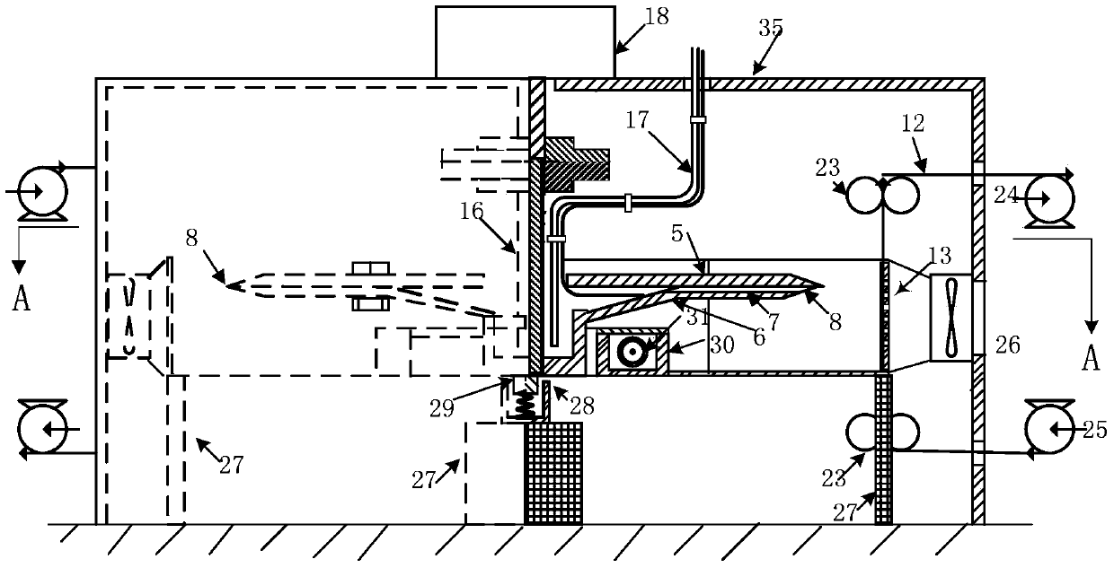
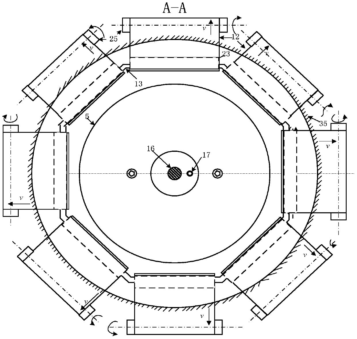
[0023] Example: Centrifugal electrostatic continuous spinning nanofiber device, such as figure 1 As shown, it includes a rotating cup 21 driven by a driving mechanism, a cover box and a cover ring 5 connected to the rotating cup 21 through a connecting piece; the rotating cup 21 includes a hollow cylindrical melting part 1, located The melting material film forming ring surface 2 at the upper end is externally connected to the annular spinning part 7 on the outer edge of the melting material film forming ring surface 2. The spinning part 7 is provided with a plurality of groups of spinning grooves 19 distributed radially, each group Spinning groove 19 comprises several passages containing melting material inlet 6 and melting material outlet 8, and each passage is bifurcated into two or more narrowed passages of width in the region of spinning part 7, and the bifurcation of passage A V-shaped cutting part is formed at the position, which is used to cut the melt film that is c...


PUM


Abstract

The invention relates to a centrifugal electrostatic continuous nanofiber spinning device, which comprises a rotary cup driven by a driving mechanism and a cover ring covering the rotary cup, wherein the rotary cup comprises a hollow columnar melted material part, a melted material membrane forming annular surface positioned at the upper end of the melted material part and an annular spinning part externally connected with the outer edge of the melted material membrane forming annular surface; multiple sets of spinning tanks are radially formed in the spinning part; each set of the spinning tank comprises multiple channels including melted material inlets and melted material outlets; the part, positioned in the spinning part, of each channel is divided into two or more sub-channels narrower than the channel; V-shaped cutting parts are formed at the forking parts of the channels. The centrifugal electrostatic continuous nanofiber spinning device has the benefits as follows: the number of the melted material inlets and the melted material outlets are in square relationship, so that efficient spinning can be realized, and meanwhile, the nanoscale-cellosilk can be spun. A centrifugal spinning technology and an electrostatic spinning technology are combined organically, so that the advantage of high efficiency of the centrifugal spinning and the advantages of controllable order degree and nanofiber collection are also achieved.

Description

technical field [0001] The invention relates to a centrifugal electrostatic continuous spinning nanofiber device. Background technique [0002] The invention patent application of the Changchun Institute of Applied Chemistry, Chinese Academy of Sciences (named "Melt and solution centrifugal spinning device for preparing nonwovens", application number "200710306660.2") discloses the small holes on the annular spacer and the wall of the rotating disk The upper spinneret (similar to the spinneret inlet and nozzle outlet described in this application document), and there is no liquid guide channel between the small hole and the spinneret. For small holes and spinnerets, the solution from one small hole may be sprayed through one spinneret, or the solution from multiple small holes may be sprayed through only one spinneret, or it may be The molten material coming out of the small hole is thrown on the wall of the rotating disk between the adjacent spinnerets, and cannot be eject...

Claims


Application Information

Patent Timeline
IPC IPC(8): D01D5/00D01D5/18
Inventor 邹守宝袁建波
Owner ZHEJIANG HUAYUAN ELECTRIC HEAT
Learn More