
Double-gear assembly provided with backlash spring and mounting method thereof

A technology of anti-backlash springs and double-plate gears, which is applied to belts/chains/gears, hoisting devices, transmission parts, etc., can solve problems such as time-consuming, labor-intensive, lack of richness, and separation, and achieve the effect of easy assembly

Inactive Publication Date: 2014-12-03
SHANGHAI RADIO EQUIP RES INST
View PDF4 Cites 5 Cited by
  • Summary
  • Abstract
  • Description
  • Claims
  • Application Information

AI Technical Summary

Problems solved by technology

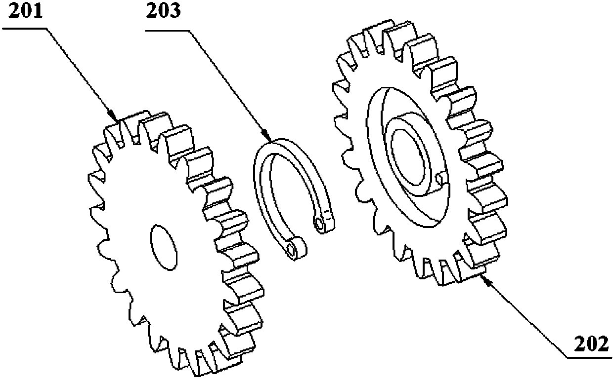
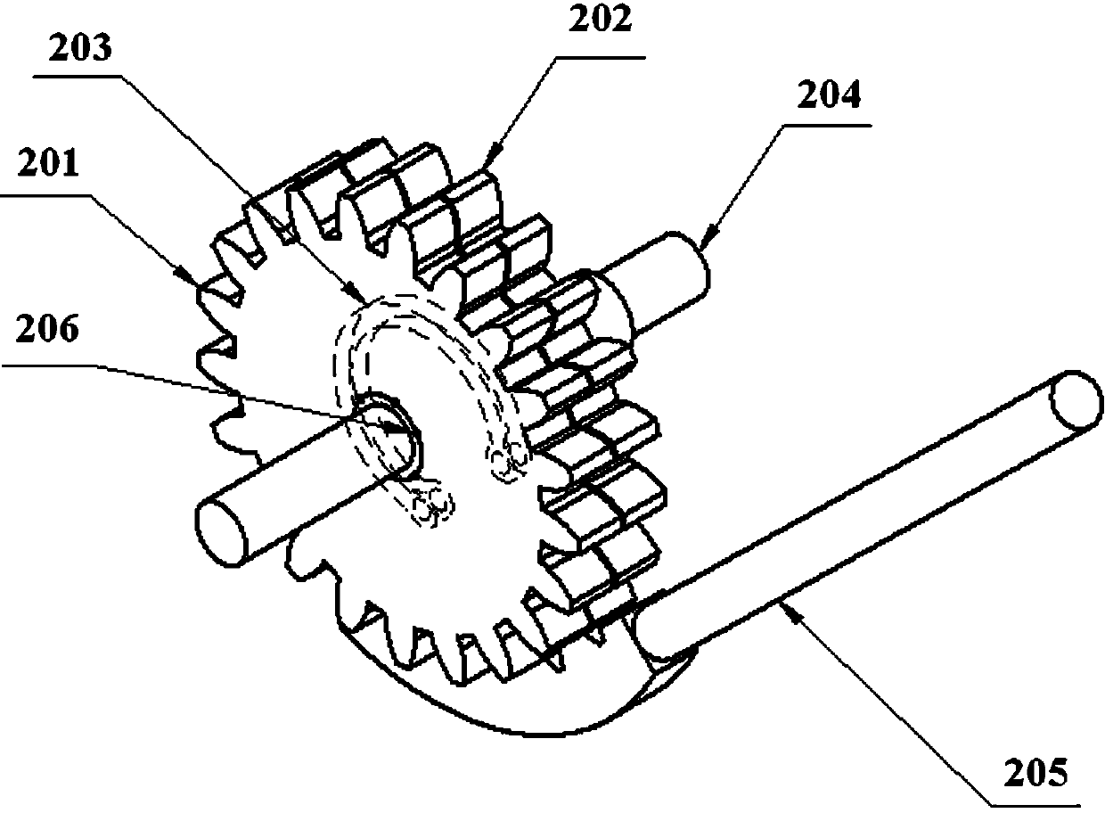
During the entire assembly process, the biggest difficulty is to keep the tooth profiles of the first gear 201 and the second gear 202 in a state of coincidence, starting from turning the second gear 202 to force the anti-backlash spring 203 to deform until the end of the assembly, the same state needs to be maintained , due to the influence of the reaction force of the anti-backlash spring 203, it is easy for the tool 205 to disengage from the second gear 202 or the second gear 202 to rotate relative to the first gear 201, resulting in the misalignment of the tooth profiles of the first and second gears. causing the assembly to fail
[0007] The biggest shortcoming of the existing assembly method is that the state of the movable gear is not easy to control
During the entire assembly process, from the time when the second gear 202 is rotated to force the anti-backlash spring 203 to deform, to the end of the assembly, the state where the tooth profiles of the first gear 201 and the second gear 202 coincide, the relative position of the tooling 205 and the gear must always be maintained Due to the influence of the reaction force of the anti-backlash spring 203, it is easy for the tooling 205 to disengage from the second gear 202 or the second gear 202 rotates relative to the first gear 201, resulting in misalignment of the tooth profiles, resulting in assembly failure. For the inexperienced operators, multiple assembly may be required, which is time-consuming and labor-intensive

Method used


Image

  • Double-gear assembly provided with backlash spring and mounting method thereof
  • Double-gear assembly provided with backlash spring and mounting method thereof
  • Double-gear assembly provided with backlash spring and mounting method thereof

Examples


Embodiment Construction

[0039] Specific embodiments of the present invention will be further described below in conjunction with the accompanying drawings.

[0040] Such as Figure 4 As shown, the present invention discloses a method for installing an anti-backlash spring double-plate gear, and the method includes the following steps:

[0041] Step 1. Prefabricate pin holes on the first gear and the second gear respectively, and the pin holes of the first gear and the second gear are respectively located on circles with the same diameter centered on their centers. The requirement for the preparation of the pin hole is that when the first gear and the second gear are in a state where a certain tooth profile overlaps, the pin holes on the first gear and the second gear also coincide accordingly.

[0042] In this embodiment, the first gear and the second gear are respectively provided with through holes with equal diameters of 3.2 as pin holes on a circle with the center as the center and a diameter of...


PUM


Abstract

The invention discloses a mounting method of a double-gear assembly provided with a backlash spring. The method comprises the steps as follows: pin holes are performed in a first gear and a second gear respectively and formed in circumferences having equal diameters and taking the centers of the first gear and the second gear as the circle centers; the first gear, the second gear and the backlash spring are arranged on a gear shaft in a sleeving manner, the backlash spring is mounted between the first gear and the second gear, and the double-gear assembly provided with the backlash spring is formed; the pin holes coincide after the first gear and the second gear rotate relatively taking the gear shaft as the center, and pins are mounted in the pin holes; the double-gear assembly provided with the backlash spring is mounted to a transmission chain; and the double-gear assembly provided with the backlash spring is separated from the pins. Through matching of the pin holes in the gears with the pins, the states of the movable gears are controlled accurately, gear profiles coincide all along, and the double-gear assembly provided with the backlash spring can be assembled to the transmission chain; and a tooling for separating the pins is designed, so that the double-gear assembly provided with the backlash spring is conveniently separated from the pins.

Description

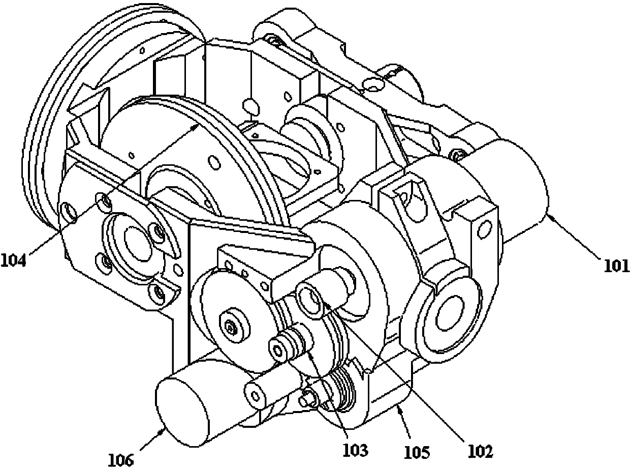
technical field [0001] The invention relates to the field of assembling gear transmission chains of reduction boxes, in particular to a backlash-removing spring double-plate gear and an installation method thereof when a position marker is assembled. Background technique [0002] As a precision servo mechanism with two degrees of freedom of yaw and pitch, the position marker transmits the output torque of the motor to the load through the gear transmission chain reducer to realize the movement of the mechanism. [0003] Such as figure 1 As shown, it is a schematic structural diagram of a typical servo mechanism gear transmission chain reduction box, which includes: a motor 101, a primary transmission gear 102 sleeved on the output shaft of the motor 101, and a secondary transmission gear meshed with the primary transmission gear 102 Gear 103, tertiary transmission gear 104 meshed with secondary transmission gear 103, potentiometer 105 transmission-connected to secondary tra...

Claims


Application Information

Patent Timeline
Patent Type & Authority Applications(China)
IPC IPC(8): F16H57/023F16H55/17F16H55/18
CPCF16H57/023F16H55/17F16H55/18F16H2700/00
Inventor 王光强夏峥成志锋
Owner SHANGHAI RADIO EQUIP RES INST
Learn More