Automobile headlamp optical system

A lighting and automotive technology, applied in the field of automotive headlight lighting systems, can solve the problems of narrow light width, dark light, low light utilization rate, etc., to improve the utilization rate of luminous flux, enhance light brightness, and light distribution effects. boosted effect

Active Publication Date: 2014-12-03
GUANGDONG RAYTON INTELLIGENT OPTO CO LTD
View PDF5 Cites 26 Cited by
  • Summary
  • Abstract
  • Description
  • Claims
  • Application Information

AI Technical Summary

Problems solved by technology

[0002] Existing LED automobile low beam headlights mostly use a projector structure, such as a kind of automobile front light low beam disclosed in Chinese utility model patent (CN201561349U), its light-emitting unit and radiator are superimposed together, and each light-emitting unit is formed by a reflector. The cup 7, the baffle 5, the lens 2 and the light source 10 are composed of the working principle: the reflective cup 7 gathers the light emitted by the LED light source 10, and the baffle 5 blocks part of the light to form a light-dark cut-off line, and then the light passes through the lens 2 After converging, a low-beam light type with cut-off line is obtained; the main disadvantages of this low-beam headlight are: ① The light is blocked by the baffle 5 and the light utilization rate of the LED light source 10 is low, that is, the light source The utilization rate of luminous flux is low; ②The light reflected by the reflective surface at the far end of the reflective cup 7, in which direction it is reflected and refracted by the lens 2, the angle of the light emitted by the refraction of the lens 2 is above 12°, and this part of the light is calculated according to the height of the lamp from the ground 0.75 m calculation (0.75 / tan12°=3.5) close to the range within 3.5m from the lamp, and this part of the light is meaningless in driving, so this part of the light is also a waste
Therefore, the illumination distance of the light of this low beam headlight is relatively short, the light width is narrow, and the light light is dark.

Method used


Image

  • Automobile headlamp optical system
  • Automobile headlamp optical system
  • Automobile headlamp optical system

Examples


Embodiment Construction

[0034] The present invention will be further described below in conjunction with the accompanying drawings of the description.

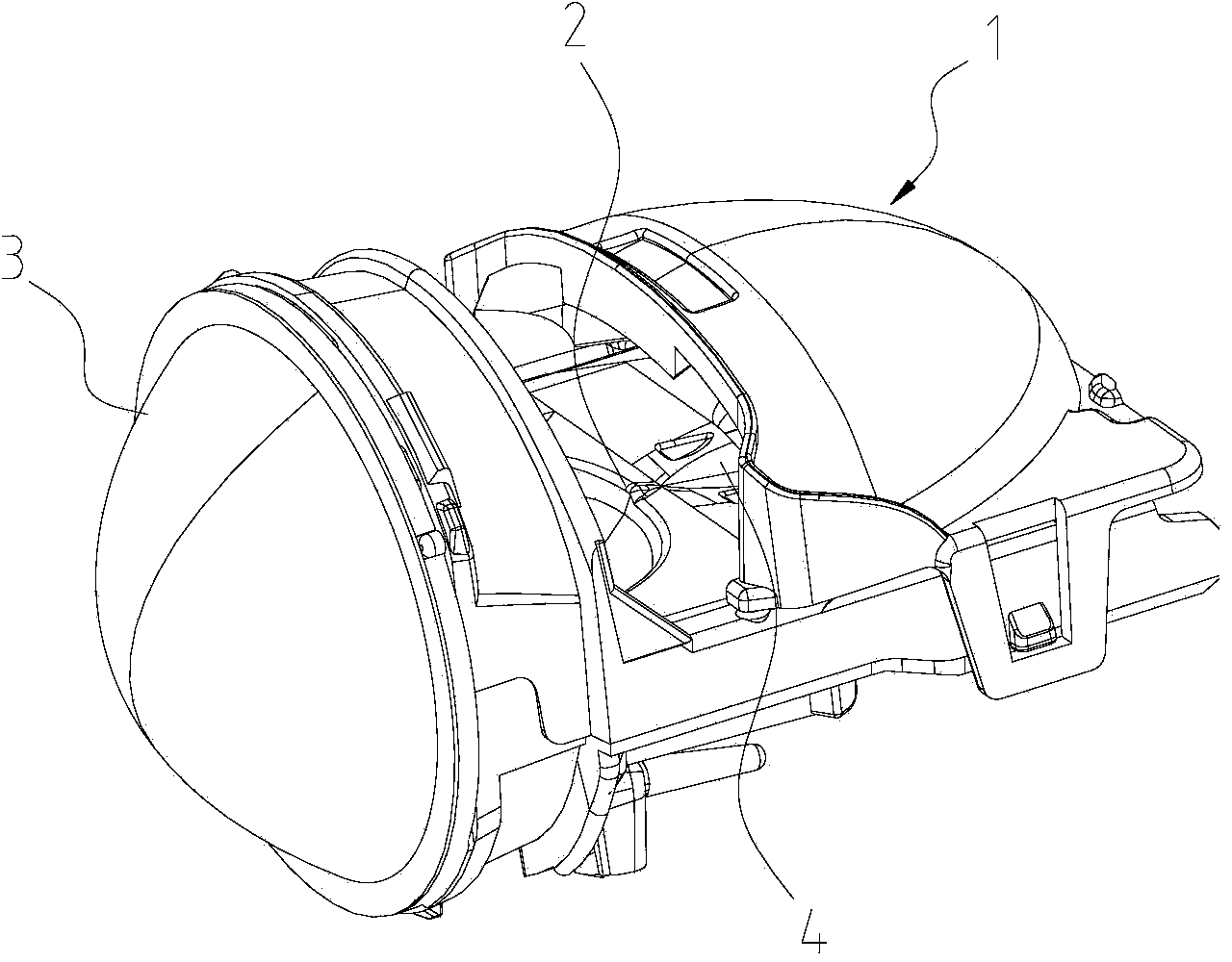
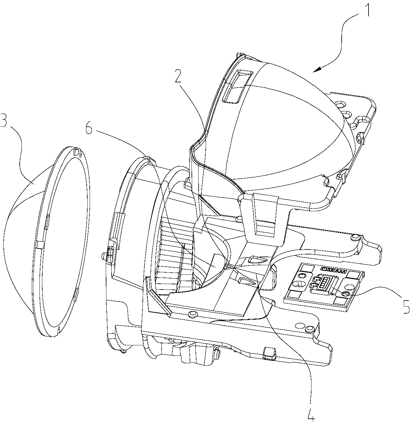
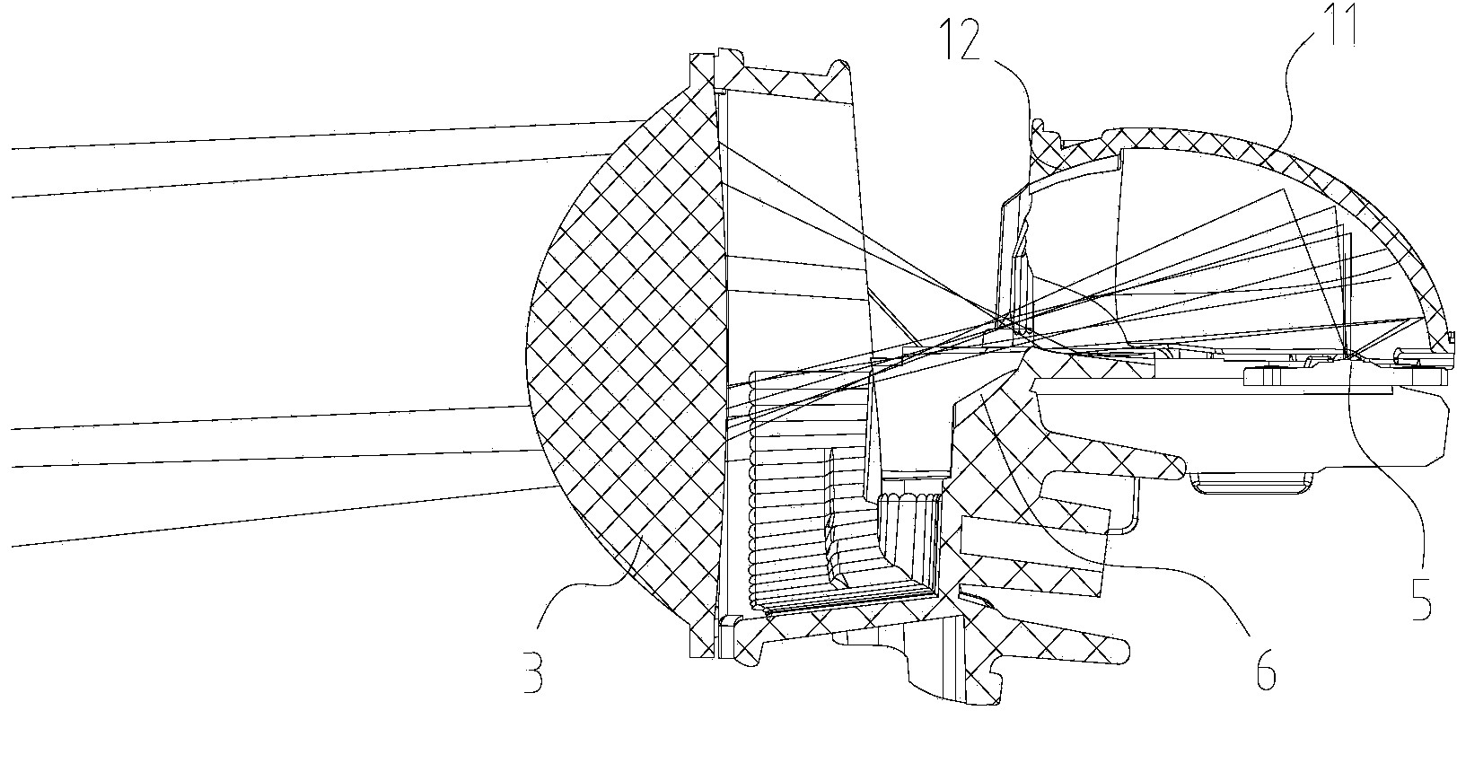
[0035] Such as Figures 1 to 3 As shown, an automotive headlight optical system includes an LED light source 5, a reflective part and a lens 3, and the reflective part includes a first reflector 1 positioned above the LED light source 5 and a reflector plate positioned below the first reflector 1 4. The baffle 2 located in front of the reflector 4 and the second reflector 6 located under the front of the baffle 2; the first reflector 1 includes a first main reflector 11 that converges and reflects light from the LED light source 5 to the lens 3 And the light from the LED light source 5 is converged and reflected to the second reflector 6 and then reflected to the first auxiliary reflector 12 of the lens 3; the part of the light blocked by the baffle 2 is reflected to the lens twice through the reflector 4 behind the baffle 2 3. To obtain the low bea...


PUM


Abstract

The invention provides an automobile headlamp optical system which comprises an LED light source, a reflection part and a lens. The reflection part comprises a first reflecting mirror, a reflecting plate, a baffle and a second reflecting mirror. The first reflecting mirror comprises a first main reflecting mirror body and a first auxiliary reflecting mirror body. The portion, on the rear of the baffle, of the reflecting plate is used for reflecting some light shielded by the baffle to the lens secondarily so that a dipped headlight light type with light and shade cut-off lines can be obtained. The first reflecting mirror is shaped like an ellipsoid. The LED light source and an optical axis are vertically arranged on a first focal point of the ellipsoid. The first reflecting mirror is the upper half portion of the ellipsoid and extends to a second focal point. The baffle is arranged on the portion, located on the second focal point of the first reflecting mirror, of the ellipsoid. The portion, on the top of the baffle, of the reflecting plate reflects some light shielded by the baffle to the lens secondarily so that a dipped headlight light type with light and shade cut-off lines can be obtained; meanwhile, most of the light shielded and filtered out is fully utilized, and the utilization rate of luminous flux is increased.

Description

technical field [0001] The invention relates to the field of LED lighting, in particular to an automotive headlight optical system. Background technique [0002] Existing LED automobile low beam headlights mostly use a projector structure, such as a kind of automobile front light low beam disclosed in Chinese utility model patent (CN201561349U), its light-emitting unit and radiator are superimposed together, and each light-emitting unit is formed by a reflector. The cup 7, the baffle 5, the lens 2 and the light source 10 are composed of the working principle: the reflective cup 7 gathers the light emitted by the LED light source 10, and the baffle 5 blocks part of the light to form a light-dark cut-off line, and then the light passes through the lens 2 After converging, a low-beam light type with cut-off line is obtained; the main disadvantages of this low-beam headlight are: ① The light is blocked by the baffle 5 and the light utilization rate of the LED light source 10 is ...

Claims


Application Information

Patent Timeline
Patent Type & Authority Applications(China)
IPC IPC(8): F21S8/10F21V13/04F21V7/08F21V5/04F21W101/02F21W101/10F21Y101/02F21W107/10
Inventor 陈焕杰
Owner GUANGDONG RAYTON INTELLIGENT OPTO CO LTD
Why Eureka
Try Eureka