
Novel gasification combustion device

A combustion device and a new type of technology, applied in the field of coal-fired furnaces, new gasification combustion devices, and boilers, can solve the problems of high manufacturing cost, troublesome maintenance and repair of gasification furnaces, and serious environmental pollution, etc., and improve energy utilization. , high environmental protection performance, good energy saving effect

Inactive Publication Date: 2014-12-03
徐万友
View PDF10 Cites 4 Cited by
  • Summary
  • Abstract
  • Description
  • Claims
  • Application Information

AI Technical Summary

Problems solved by technology

[0002] As we all know, coal is still used for heating in northern rural areas in winter. By burning fossil energy—coal, a large amount of smoke and dust will be generated during the coal combustion process. People's health, at the same time, a large amount of smoke and dust are discharged through the flue, resulting in insufficient coal combustion, low energy utilization rate, and serious energy waste
[0003] At present, with the continuous improvement of heating furnaces, heating furnaces with gasification tubes have also emerged as the times require, and have been affirmed and recognized by the market. The preparation process of heating furnaces with air injection holes added to the furnace and gasification tubes is complicated, especially It is the ventilation hole on the furnace, which is easily blocked by coal powder, which affects the gasification effect of the heating furnace, and the later maintenance and repair are troublesome, and a large amount of heat is directly discharged into the atmosphere through the flue, resulting in energy consumption. waste. In addition, due to the high manufacturing cost of the current gasifier, the selling price is relatively high, and the market share is not very high.

Method used


Image

  • Novel gasification combustion device
  • Novel gasification combustion device
  • Novel gasification combustion device

Examples


Embodiment Construction

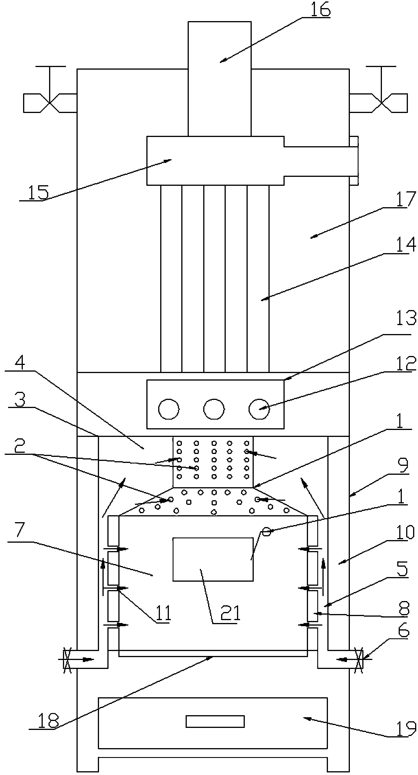
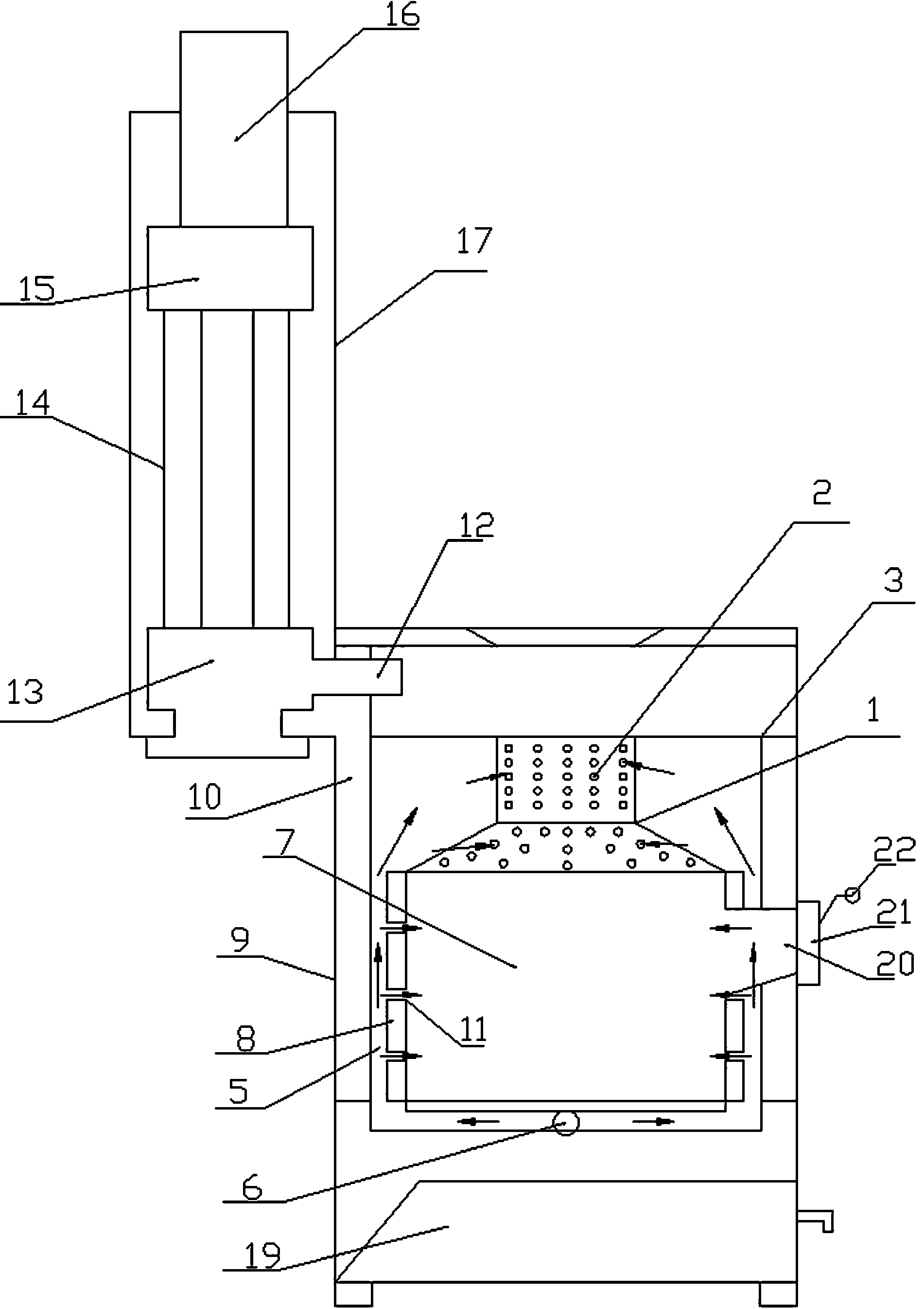
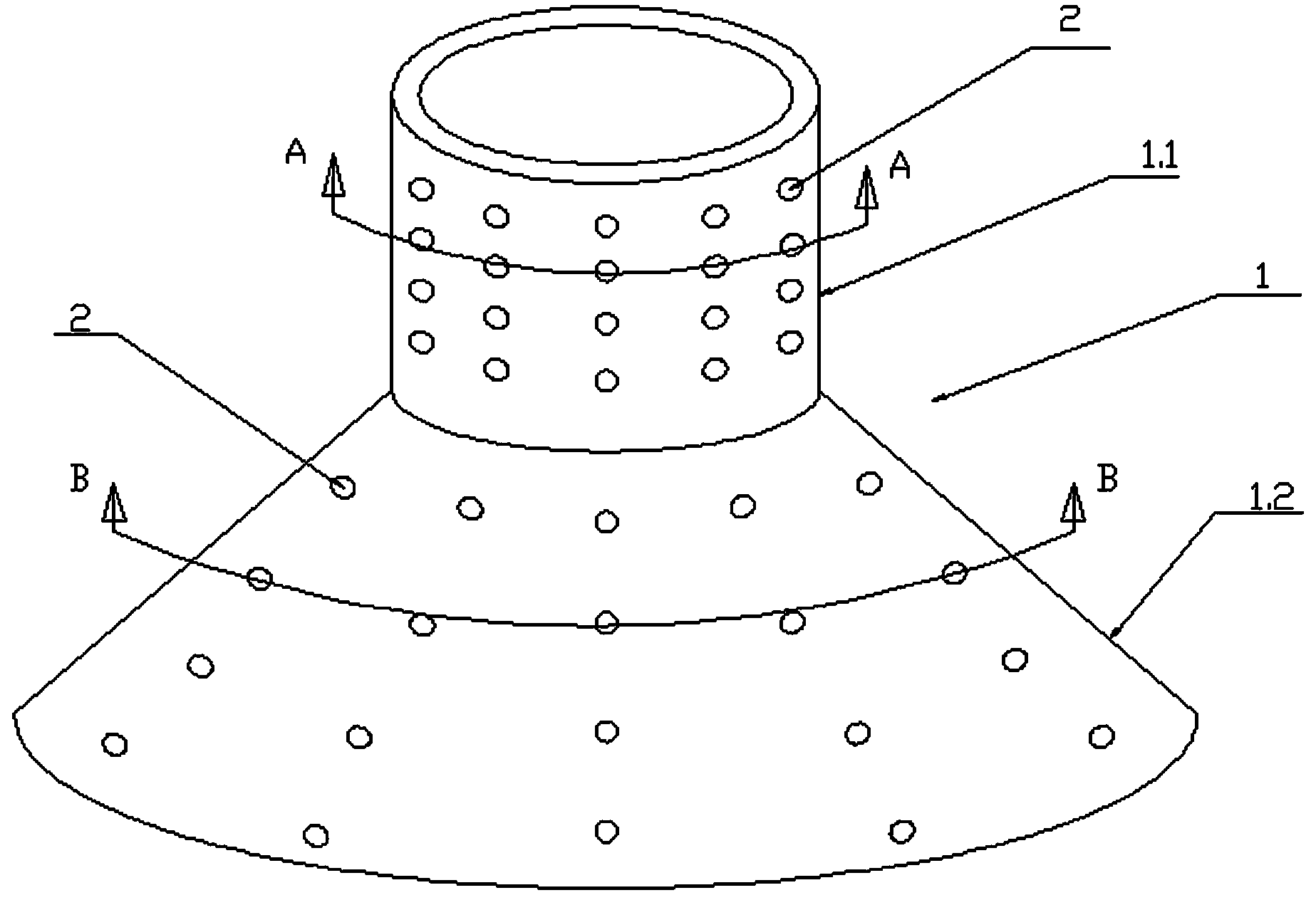
[0023] For ease of description, the novel gasification combustion device of the invention will be described in detail below in conjunction with the accompanying drawings.

[0024] like Figure 1 to Figure 5 As shown in , a new type of gasification combustion device includes a gasification cylinder 1, the surface of the gasification cylinder 1 is provided with a gasification hole 2, and the direction of the gasification hole 2 can form a gasification cylinder 1 inside. Swirling air flow; the gasification cylinder 1 includes a first part 1.1 and a second part 1.2, the first part 1.1 is a straight cylindrical structure, the second part 1.2 is a trumpet-shaped structure with a large lower end and a small top end, and the top of the second part 1.2 is connected to the first part 1.1 Connected, the gasification cylinder has a small top and a large bottom structure, which is convenient to form an upward self-suction force. In addition, the size of the upper part becomes smaller, ...


PUM


Abstract

The invention provides a novel gasification combustion device which comprises a gasification barrel. The surface of the gasification barrel is provided with gasification holes enabling a rotary air flow to be formed in the gasification barrel. The gasification barrel comprises a first part and a second part. The first part is of a straight barrel structure. The second part is of a big-end-down horn structure. The top end of the second part is connected with the first part. The gasification holes are evenly formed in the first part and the second part. The air outlet direction of the gasification holes in the first part is opposite to or the same as the air outlet direction of the gasification holes in the second part. The novel gasification combustion device has the advantages that the structure is simple, manufacturing is convenient, the manufacturing cost is low, the gasification effect is good, heat is centralized, and the energy utilization rate is improved by 15% to 30%.

Description

technical field [0001] The invention relates to the field of mechanical design, in particular to the technology of boilers and coal-fired furnaces, in particular to a novel gasification combustion device. Background technique [0002] As we all know, coal is still used for heating in northern rural areas in winter. By burning fossil energy—coal, a large amount of smoke and dust will be generated during the coal combustion process. People's health, at the same time, a large amount of smoke and dust is discharged through the flue, resulting in insufficient coal combustion, low energy utilization rate, and serious energy waste. [0003] At present, with the continuous improvement of heating furnaces, heating furnaces with gasification tubes have also emerged as the times require, and have been affirmed and recognized by the market. The preparation process of heating furnaces with air injection holes added to the furnace and gasification tubes is complicated, especially It is t...

Claims


Application Information

Patent Timeline
IPC IPC(8): F23B70/00
Inventor 徐万友
Owner 徐万友
Learn More