Baffles and Welded Plate Heat Exchangers

A technology of baffles and components, which is applied in the field of welded plate heat exchangers, can solve the problems of complicated baffle operation process, affecting the heat exchange effect of the heat exchanger, and fluid not participating in heat exchange, so as to eliminate the existence of welded structures The effect of reducing the risk, convenient and quick assembly, and improving the overall strength

Inactive Publication Date: 2016-01-20
SHANDONG WINTECH TECH CO LTD
View PDF6 Cites 2 Cited by
  • Summary
  • Abstract
  • Description
  • Claims
  • Application Information

AI Technical Summary

Problems solved by technology

[0003] While prolonging the fluid flow length in this way, since the baffle plays the role of changing the flow direction of the fluid, when the fluid flows in the flow channel, it will generate a punching force on the baffle, and the baffle will often be deformed under the action of this punching force In severe cases, it will cause a large amount of fluid leakage, which will cause a short circuit phenomenon in the flow direction of the fluid, so that part of the fluid does not participate in heat exchange, thus affecting the heat exchange effect of the heat exchanger, and finally cannot reach the temperature specified by the design.
Therefore, the thickness of the baffle in the existing structure will be increased to reduce deformation, but this measure will increase the weight of the equipment, thereby increasing the cost input
[0004] In addition, in the prior art, the baffles are usually connected to the plate bundle by welding. Because of the welding of the thin plate and the thick plate, it is easy to cause deformation of the plate bundle. At the same time, due to the welded structure, the operation process of the baffle is complicated and can be maintained. bad sex
Especially for the channel structure formed by butt jointing of plates, the channel structure is generally formed by butt jointing of plates with a thickness of 0.6-2mm. It is very easy to burn through the channel, which will cause irreparable quality problems. Obviously, this solution is not advisable

Method used


Image

  • Baffles and Welded Plate Heat Exchangers
  • Baffles and Welded Plate Heat Exchangers
  • Baffles and Welded Plate Heat Exchangers

Examples


Embodiment Construction

[0018] Embodiments of the present invention are further described below in conjunction with accompanying drawings:

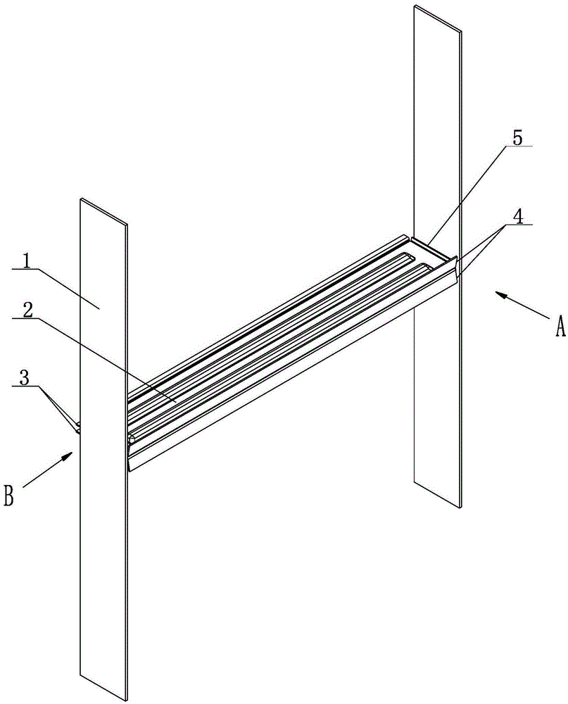
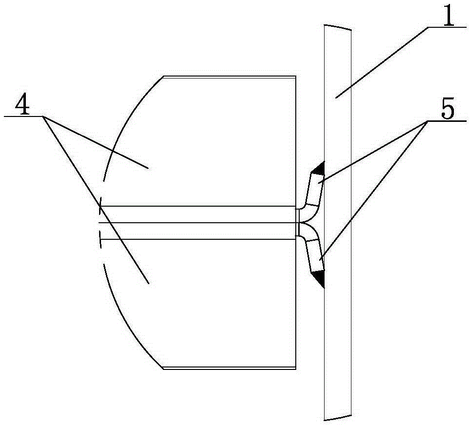
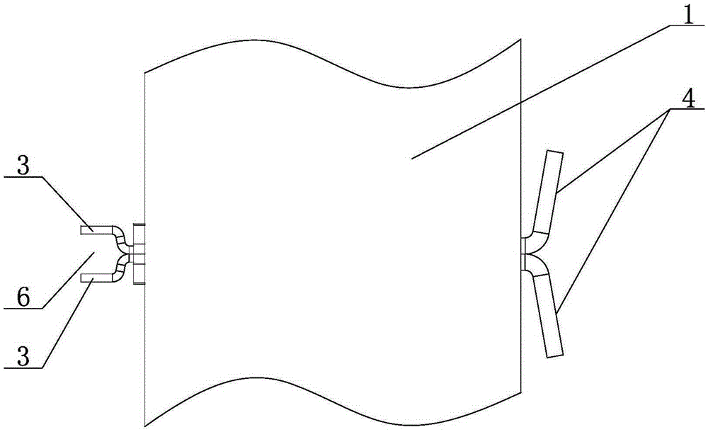
[0019] Such as Figure 1~3 As shown, the baffle assembly is composed of a baffle plate and two side plates 1. The baffle plate is welded by two corrugated plates 2 crest-to-peak (back-to-back), and the four sides of the corrugated plate 2 have hems. The side panels 1 are welded to the flanges 5 on the left and right sides of the two corrugated plates in the baffle respectively, the side plate 1 is perpendicular to the baffle, and the flanges 3 on the rear side of the two corrugated plates jointly form a bayonet 6.

[0020] In this baffle assembly, after the two corrugated plates are welded together, the shape of the bayonet 6 formed by the combination of the folded edges 3 on the rear side of the two corrugated plates matches the shape of the flow channel 15 on the side of the plate, so that it can be clamped on the Above the flow channel 15 on the side of the...


PUM


Abstract

The invention belongs to the field of heat-exchange devices, and particularly relates to a baffling assembly. The baffling assembly consists of a baffling plate and two side plates, wherein the baffling plate is formed by welding of two corrugated plates in a crest-to-crest manner; turned edges are arranged on four edges of each corrugated plate; the two side plates are welded with the turned edges on left and right sides of the two corrugated plates in the baffling plate; the side plates are perpendicular to the baffling plate; a bayonet is formed by the turned edges on back sides of the two corrugated plates. The invention further relates to a welded plate-type heat exchanger. The welded plate-type heat exchanger comprises a frame, a press plate, a heat-exchange core and the baffling assembly, wherein the two side plates in the baffling assembly are mounted on inner walls of the frame in parallel; the bayonet formed by the turned edges on the back sides of the two corrugated plates is clamped on a plate-side runner in the middle of the heat-exchange core; the turned edges on front sides of the two corrugated plates are fit with the press plate. By the aid of the baffling assembly, the strength of the baffling plate can be enhanced, deformation caused by fluid scouring can be prevented, and the baffling assembly is convenient to assemble; the welded plate-type heat exchanger provided with the baffling assembly also has the technical effects.

Description

technical field [0001] The invention relates to a baffle assembly and a welded plate heat exchanger using the baffle assembly, belonging to the field of heat exchange devices. Background technique [0002] In the existing welded plate heat exchanger, in order to increase the flow length of the fluid in the heat exchanger and improve the heat exchange effect, a baffle plate is often installed in the flow channel on one side of the heat exchanger so that the fluid in the flow channel is in the shell. S-shaped flow. [0003] While prolonging the fluid flow length in this way, since the baffle plays the role of changing the flow direction of the fluid, when the fluid flows in the flow channel, it will generate a punching force on the baffle, and the baffle will often be deformed under the action of this punching force , In severe cases, it will cause a large amount of fluid leakage, which will cause a short circuit phenomenon in the flow direction of the fluid, so that part of ...

Claims


Application Information

Patent Timeline
Patent Type & Authority Patents(China)
IPC IPC(8): F28F9/24F28D9/00
Inventor 杨立勇
Owner SHANDONG WINTECH TECH CO LTD
Why Eureka
Try Eureka