Ranging passive location method under azimuth angle prior condition based on linear sparse arrays

A technology of passive positioning and azimuth, which is applied in the field of electronic information and can solve problems such as application limitations of single-station passive positioning methods

Active Publication Date: 2014-12-03
齐鲁电科山东科技成果转化有限公司
View PDF3 Cites 21 Cited by
  • Summary
  • Abstract
  • Description
  • Claims
  • Application Information

AI Technical Summary

Problems solved by technology

As a result, observability issues often lead to limitations in t

Method used


Image

  • Ranging passive location method under azimuth angle prior condition based on linear sparse arrays
  • Ranging passive location method under azimuth angle prior condition based on linear sparse arrays
  • Ranging passive location method under azimuth angle prior condition based on linear sparse arrays

Examples


Embodiment

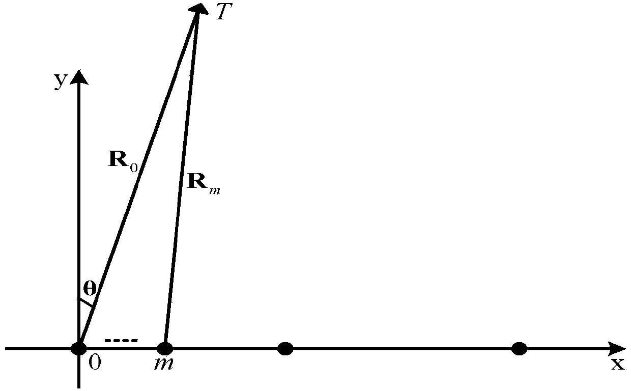
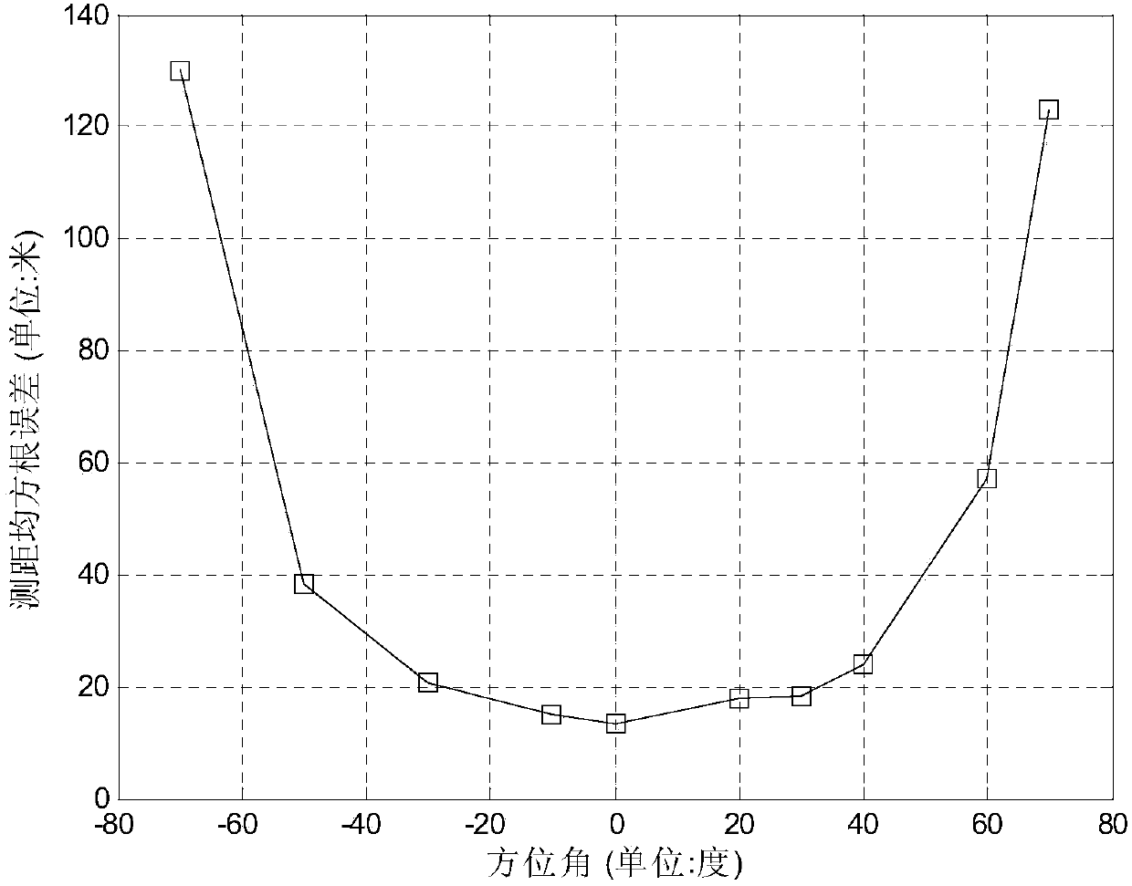
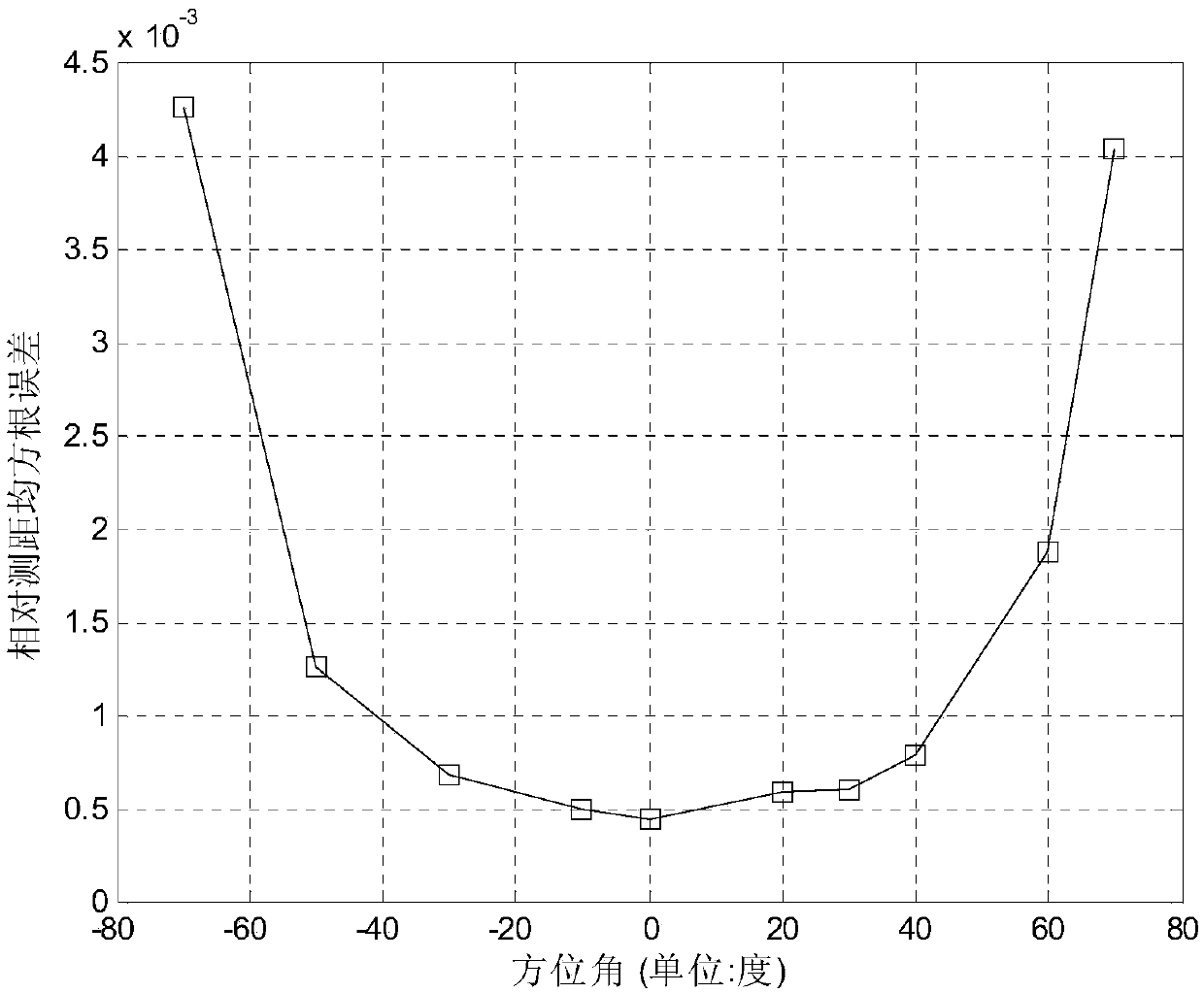
[0066] This embodiment takes 7 observation stations sparsely arranged on a straight line, the working wavelength of the near-field radiation source is 3 cm and the distance from the observation station is 30.5 kilometers as an example, that is, M=7, λ=3cm, R 0 = 30.5 km. With the leftmost observation station on the straight line as the coordinate origin, and the straight line where the observation station is located as the abscissa axis, a right-handed rectangular coordinate system is established. The distances between the remaining six observation stations and the origin of the coordinates are d 1 = 10m, d 2 =20m,d 3 = 35m, d 4 =60m,d 5 =83m,d 6= 100m. The total length of observation data received in this example is N=1000, and the signal-to-noise ratio is 15dB. Investigate that the near-field radiation source is incident on the observatory at 10 azimuth angles θ=-70°, -50°, -30°, -10°, 0°, 20°, 30°, 40°, 60°, and 70° The distance measuring performance of the present ...


PUM


Abstract

The invention provides a ranging passive location method under an azimuth angle prior condition based on linear sparse arrays. The features of a multi-station system and a single-station system of passive location are combined, on the basis that observing stations are arrayed in a small space range in a linear sparse array mode, the observing stations are used for receiving data phase information, and near-field radiation source ranging location is achieved. On the basis of meticulous analysis of a structure of observed data phase information, prior azimuth angle information is used for carrying out phase compensation on a phase fuzzy part existing in the observed data phase information, a non-phase fuzzy part existing in the observed data phase information is used for establishing an array signal model, and estimation of near-field radiation source distance is completed based on a MUSIC algorithm.

Description

technical field [0001] The invention relates to electronic information technology, in particular to a near-field radiation source passive positioning technology. Background technique [0002] Passive positioning refers to passively receiving electromagnetic wave signals from near-field radiation sources under the condition that the observation equipment itself does not radiate electromagnetic waves, and using the space in the sense of direction and distance between the observation equipment and the radiation source in a certain coordinate system With respect to the geometric relationship and its changes, by measuring the angle of arrival, time difference of arrival and / or changes in other corresponding physical quantities carried in the electromagnetic wave signal of the radiation source, the target position, velocity and acceleration of the radiation source are calculated, and the target positioning is finally realized covertly . [0003] The passive positioning system is ...

Claims


Application Information

Patent Timeline
IPC IPC(8): G01S5/02
CPCG01S5/02
Inventor 殷吉昊刘梦晗万群
Owner 齐鲁电科山东科技成果转化有限公司
Why Eureka
Try Eureka