A Folded Waveguide Slow-Wave Structure with Decreasing Electron Beam Channels

A technology of electron injection channel and slow wave structure, which is applied to the circuit components of transit time electron tubes, etc., can solve the problems of high precision processing technology and high centering requirements, reduce coupling impedance, low flow rate and other problems, and avoid Decreased power performance, improved output power performance, and improved interaction impedance

Active Publication Date: 2019-06-14
NO 12 RES INST OF CETC
View PDF3 Cites 0 Cited by
  • Summary
  • Abstract
  • Description
  • Claims
  • Application Information

AI Technical Summary

Problems solved by technology

Therefore, in order to obtain high power output, technical issues such as high current density current generation and maintenance, high precision processing technology and high alignment requirements are limited
At the current level of technology, when the electron beam passes through the slow-wave structure, serious interception will occur, and the low flow rate caused by the interception will reduce key performance indicators such as power and efficiency of the device.
Although in actual development, the flow rate can be increased by concentrating the electron beam at the center of the electron beam channel, but this design method will still limit the output power of the device due to the significant reduction in the coupling impedance away from the boundary of the electron beam channel.

Method used


Image

  • A Folded Waveguide Slow-Wave Structure with Decreasing Electron Beam Channels
  • A Folded Waveguide Slow-Wave Structure with Decreasing Electron Beam Channels
  • A Folded Waveguide Slow-Wave Structure with Decreasing Electron Beam Channels

Examples


Embodiment Construction

[0016] specific implementation plan

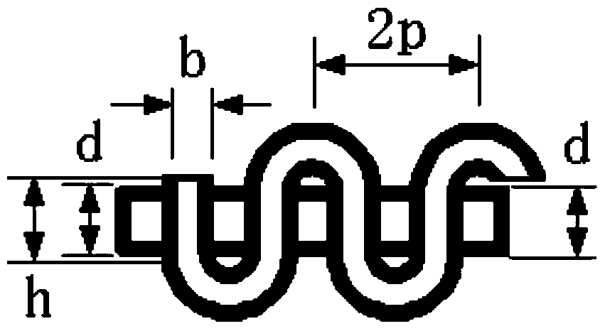
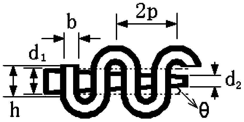
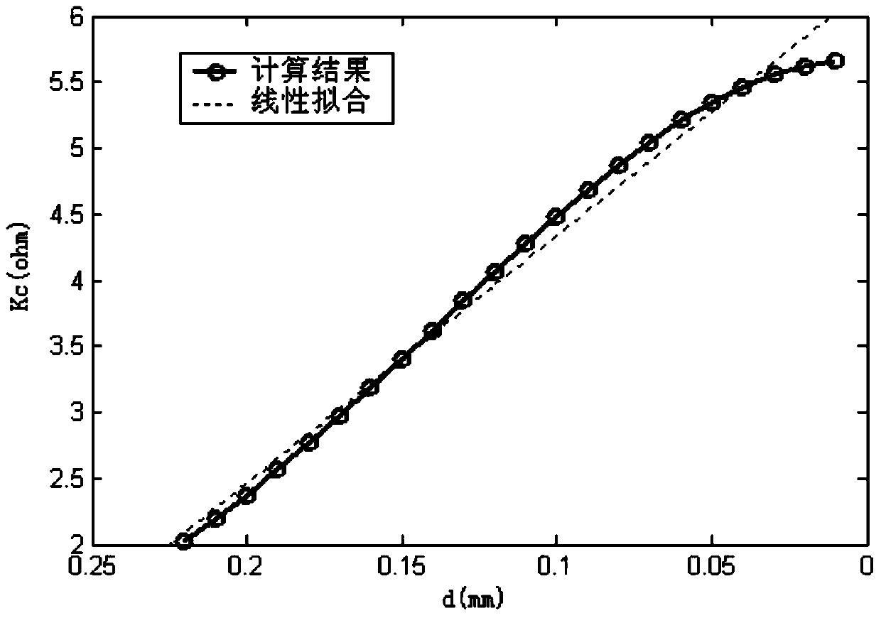
[0017] In order to clearly illustrate the effect of this folded waveguide slow-wave structure with radial size decreasing electron beam channels, the following example is given, setting the structure size a=1.9mm, b=0.3mm, p=0.7mm, h=0.7 mm, d=0.44mm. The three-dimensional electromagnetic software is used to simulate the all-metal slow wave structure of the electron beam channel with radial size decreasing in the present invention, and the size of the electron beam channel and the coupling impedance at different positions in the channel are calculated, and the full-metal slow wave structure using the convergent electron beam channel is simulated. The performance of the metal slow-wave structure device. At this time, the diameter of the entrance of the electron injection channel is 0.44mm, and the exit is 0.16mm in a conical shape. Comparing the simulation results with the injection wave interaction results of the traditional slow-wave str...


PUM


Abstract

The invention discloses a folding waveguide slow-wave structure provided with an electron beam channel with a progressively decreasing internal diameter dimension and belongs to the field of microwave vacuum electronic devices. Along the axis of the slow-wave structure, the electron beam channel changes from a traditional uniform cylinder into a cone, the internal diameter dimension of which progressively changes. The cross section size of the electron beam channel progressively decreases in the longitudinal direction so that gradual strengthening of the intensity of an electromagnetic field in the longitudinal direction in an interactive area is formed. Through simulation selection and adjustment of the radial dimension, angle optimization of the progressively decreasing electron beam channel is realized so as to realize more sufficient hand-over of energy by electron beams in the channel to the electromagnetic field so that an interactive impendence is improved and the electron beams gradually approach a high field area at the edge of the electron beam channel and thus an output power performance of the device is improved.

Description

technical field [0001] The invention belongs to the field of microwave vacuum electronic devices, and in particular relates to a folded waveguide slow-wave structure with electron injection channels of decreasing size. Background technique [0002] In the short millimeter wave band (40GHz-300GHz) and terahertz frequency domain (300GHz-3000GHz), high-power and miniaturized terahertz vacuum radiation sources can be generated by using linear injection vacuum electronic devices, such as return wave oscillators, extended interaction devices and traveling wave devices, etc. With the increase of operating frequency, the characteristic size of the slow wave structure gradually decreases. Therefore, in order to obtain high power output, there are limitations on technical issues such as high current density current generation and maintenance, high precision processing technology and high alignment requirements. At the current level of technology, when the electron beam passes throug...

Claims


Application Information

Patent Timeline
Patent Type & Authority Patents(China)
IPC IPC(8): H01J23/24
Inventor 蔡军冯进军邬显平
Owner NO 12 RES INST OF CETC
Why Eureka
Try Eureka