Push-pull converter
A technology of converters and transformers, applied in the field of switching power supplies, which can solve problems such as slow start-up process and complicated drive circuit design
- Summary
- Abstract
- Description
- Claims
- Application Information
AI Technical Summary
Problems solved by technology
Method used
Image
Examples
Embodiment Construction
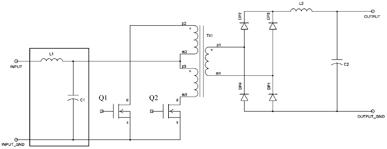
[0012] figure 1 It is the circuit diagram of Embodiment 1 of the push-pull converter of the present invention, the push-pull converter includes transformer TX1, MOS transistors Q1, Q2, columnar high-frequency inductor L1, high-frequency film capacitor C1, rectifier module, filter inductor L2 and output capacitor C2 , and, the rectification module is a diode rectification bridge composed of four diodes DP1, DP2, DP3 and DP4. Among them, on the primary side of the transformer TX1, the sources of the MOS transistors Q1 and Q2 share the ground, and the drains of the MOS transistors Q1 and Q2 are respectively connected to the two ends (p2 and m3) of the primary winding of the transformer TX1. What needs to be explained here Yes, the gates of the MOS transistors Q1 and Q2 are connected to a driving circuit (not shown). The first end of the columnar high-frequency inductor L1 is connected to the positive terminal (INPUT) of the input power supply, the negative terminal (INPUT_GND) o...
PUM
 Abstract
Description
Claims
Application Information
 - R&D
- Intellectual Property
- Life Sciences
- Materials
- Tech Scout
- Unparalleled Data Quality
- Higher Quality Content
- 60% Fewer Hallucinations
Browse by: Latest US Patents, China's latest patents, Technical Efficacy Thesaurus, Application Domain, Technology Topic, Popular Technical Reports.
© 2025 PatSnap. All rights reserved.Legal|Privacy policy|Modern Slavery Act Transparency Statement|Sitemap|About US| Contact US: help@patsnap.com

