Supercharge Your Innovation With Domain-Expert AI Agents!

Large-power mixed cascading bridge-type unit power factor rectifier

A unit power factor, hybrid cascading technology, applied in the field of rectifiers, can solve the problems of power factor reduction, circuit structure complexity, adding rectifiers, etc.

Active Publication Date: 2014-12-03
CHINA UNIV OF MINING & TECH (BEIJING)
View PDF6 Cites 5 Cited by
  • Summary
  • Abstract
  • Description
  • Claims
  • Application Information

AI Technical Summary

Problems solved by technology

However, the cascaded multilevel circuit topology proposed by these two patents has a common problem, that is, these two types of multilevel converters cannot realize true unity power factor rectification, and the power factor will vary with the DC The increase of the load connected to the terminal reduces the
[0005] In order to solve the problem of unity power factor operation, the patent "High Power Compensated Cascaded Diode H-Bridge Unity Power Factor Rectifier" (201410090383.6) proposes to add series compensation, or parallel compensation; or series compensation to the diode H-bridge cascaded multilevel rectifier. The compensation link is connected in parallel, and the compensation link is adjusted and controlled according to the change of the load, so that the diode H-bridge cascaded multilevel rectifier can always operate at unity power factor regardless of the load change, but the problem of this patent Yes, series compensation, or parallel compensation; or series-parallel compensation links need to be connected to the diode H-bridge cascaded multilevel rectifier through a power frequency transformer. The original intention of the power frequency transformer is inconsistent, and this solution undoubtedly increases the volume, weight, and complexity of the circuit structure and circuit control of the rectifier

Method used


Image

  • Large-power mixed cascading bridge-type unit power factor rectifier
  • Large-power mixed cascading bridge-type unit power factor rectifier
  • Large-power mixed cascading bridge-type unit power factor rectifier

Examples


Embodiment Construction

[0083] In the embodiment of the high-power hybrid cascaded bridge-type rectifier with unity power factor of the present invention, the high-power hybrid cascaded bridge-type rectifier with unity power factor is an overall circuit topology formed by cascading several modules. The cascaded modules include a first module A, a second module B, a third module C and a fourth module D, wherein:

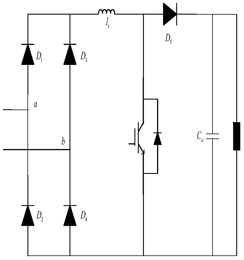
[0084] refer to figure 1 , the first module A includes a switching device IGBT, a fast recovery diode D 0 , Output DC capacitance C 0 and load R 0 .

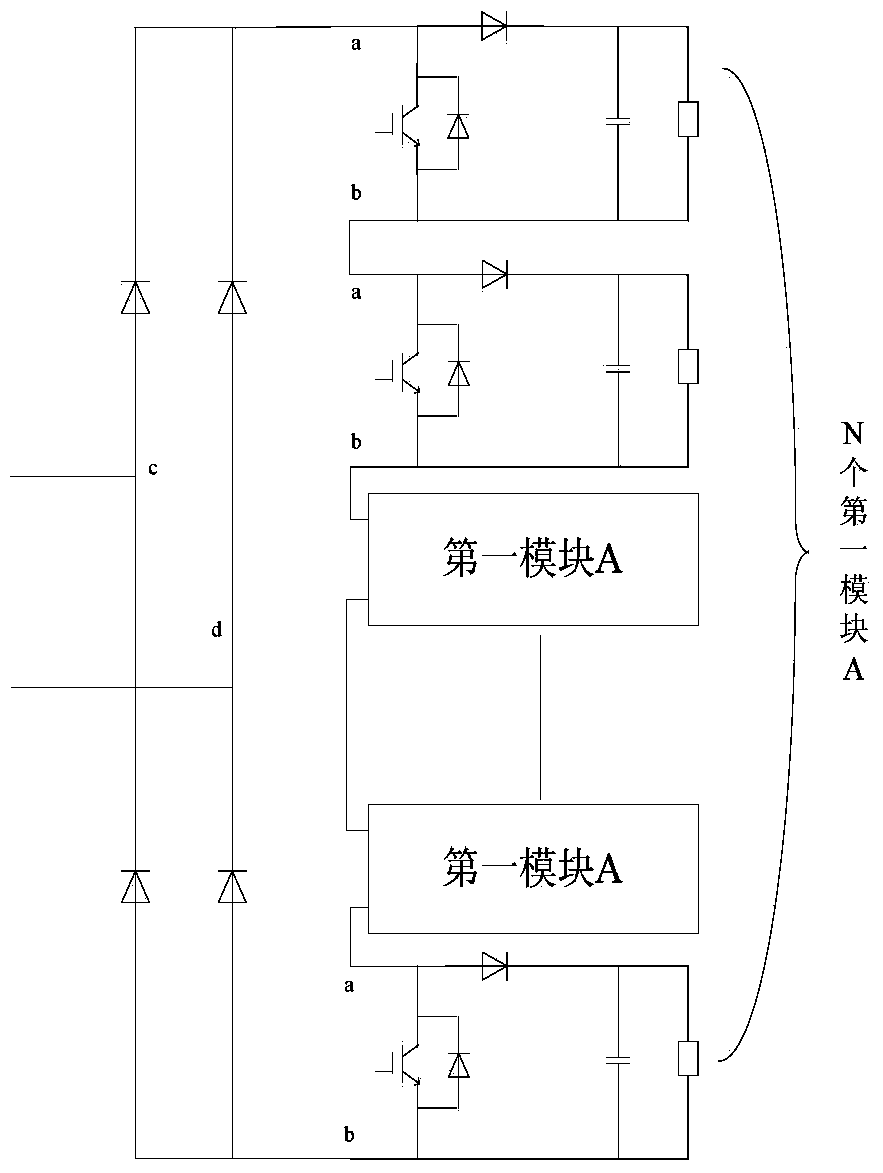
[0085] refer to figure 2 , the second module B includes a diode rectifier bridge and N cascaded first modules A.

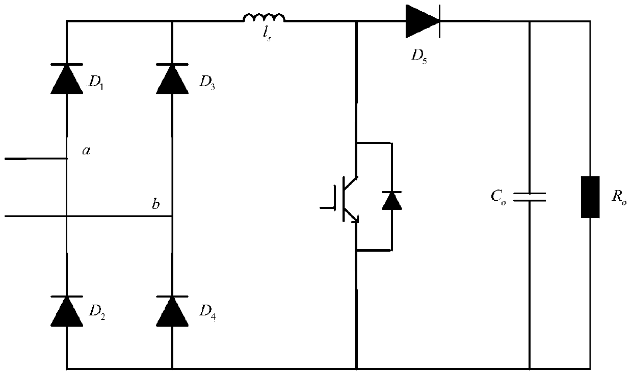
[0086] refer to image 3 , the third module C includes a single-phase fully-controlled bridge rectifier circuit composed of a fully-controlled device IGBT, an output DC capacitor C 1 and load R 1 , the output terminal of the full-controlled bridge rectifier circuit is connected with the output DC capacitor and the load co...


PUM


Abstract

The invention relates to a large-power mixed cascading bridge-type unit power factor rectifier. A main power circuit comprises a boosting inductor and cascading modules, the cascading modules include first to sixth modules, and cascading of the main power circuit of the unit power factor rectifier is in a single-phase bridge type, three-phase star connection, corner connection or double-star connection manners. The rectifier has the advantages that use of a power-frequency transformer is not required, power switch tubes of lower withstand voltage can be used to realize large-power rectification and transformation under a high voltage, and the amount of used fully-controlled switching elements is greatly reduced; the rectifier can operate in advanced, lagged, unit power factor and other conditions; the topology structure of the main power circuit is simplified, the cost is reduced, the efficiency is improved, the control complexity is reduced, and system control is simple; and the rectifier has great application values in the fields including high-voltage DC power transmission, large-power electronic power transformers, and large-power middle / high-voltage AC-DC-AC frequency converter.

Description

technical field [0001] The invention relates to a rectifier, in particular to a high-power hybrid cascaded bridge-type rectifier with unit power factor. Background technique [0002] With the rapid development of science and technology and industrial modernization and the requirement for energy conservation, medium and high voltage power electronic converters used in high-power applications play an increasingly important role. In recent years, multilevel power converters (Multilevel Converter) have been successfully applied in the fields of high voltage and high power frequency conversion speed regulation, active power filter devices, high voltage direct current (HVDC) transmission systems and power system reactive power compensation. The basic circuit topologies of multilevel converters mainly include diode clamping, flying capacitor, and power unit cascading circuits. Among them, the power unit cascaded multilevel converter has become the mainstream of the market because ...

Claims


Application Information

Patent Timeline
Patent Type & Authority Applications(China)
IPC IPC(8): H02M7/219H02M1/42
CPCY02B70/10Y02P80/10
Inventor 王聪程红王畅蒋向北焦健卢其威邹甲
Owner CHINA UNIV OF MINING & TECH (BEIJING)
Features
  • R&D
  • Intellectual Property
  • Life Sciences
  • Materials
  • Tech Scout
  • Unparalleled Data Quality
  • Higher Quality Content
  • 60% Fewer Hallucinations
Learn More