Channel information feedback method and device in mobile communication system

A technology of system bandwidth and system equipment, applied in the field of mobile communication, can solve a large number of problems such as computational complexity

Active Publication Date: 2014-12-03
SHANGHAI LANGBO COMM TECH CO LTD
View PDF6 Cites 52 Cited by
  • Summary
  • Abstract
  • Description
  • Claims
  • Application Information

AI Technical Summary

Problems solved by technology

[0012] 1. Pilot pollution-the channel estimation of the target SRS will be interfered by other SRS sequences, especially the interference from the non-orthogonal SRS of adjacent cells, so that the CIR estimated by the system side includes the interference component directed to the UE in the adjacent cell , forming inter-cell interference
[0013] 2. Complexity - The number of antennas in a Massive MIMO system may reach hundreds, and each antenna independently estimates the CIR requires a lot of computational complexity

Method used


Image

  • Channel information feedback method and device in mobile communication system
  • Channel information feedback method and device in mobile communication system
  • Channel information feedback method and device in mobile communication system

Examples


Embodiment 1

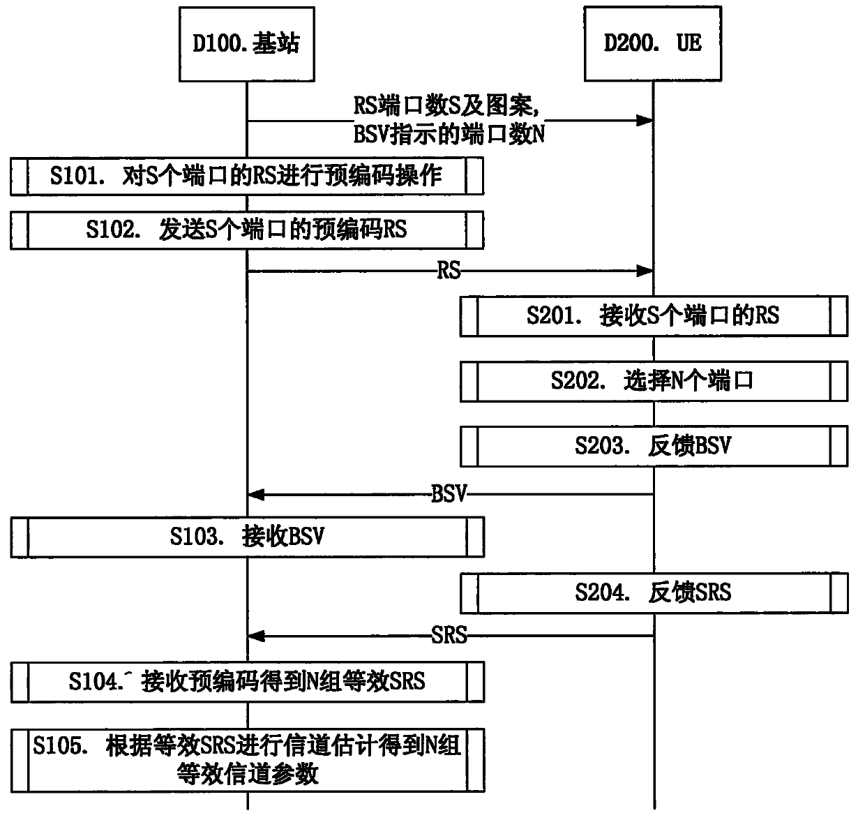
[0108] Embodiment 1 is a flowchart of the interaction between the base station and the UE, as shown in the attached image 3 shown. attached image 3 In , the downlink reference signal port S and the corresponding pattern and the port number N indicated by the BSV are configured by signaling.

[0109] The base station device D100 performs a precoding operation on the downlink reference signals of S ports in step S101, and sends the downlink reference signals of the S ports to the UE device D200 in step S102. UE device D200 receives downlink reference signals within the system bandwidth of the S ports in step S201, then selects N ports with better transmission quality within the system bandwidth in step S202, and then feeds back BSV in step S203. The base station apparatus D100 receives BSV in step S103. The UE device D200 feeds back the SRS in step S204, and the base station device D100 performs reception precoding on the SRS according to the precoding vector of the BSV ind...

Embodiment 2

[0112] Embodiment 2 is a structural block diagram of a processing device used in UE, as shown in the attached Figure 4 shown. attached Figure 4 Among them, the UE device 300 is composed of a receiving device 301 , a selecting device 302 , and a sending device 303 . The receiving means 301 receives downlink reference signals of S ports, the selecting means 302 selects N ports with better channel quality according to RSRP or RSRQ, and the sending means 303 sends BSV indicating the indexes of the N ports.

Embodiment 3

[0114] Embodiment 3 is a structural block diagram of a processing device used in UE, as shown in the attached Figure 4 shown. attached Figure 4 Among them, the UE device 300 is composed of a receiving device 301 , a selecting device 302 , and a sending device 303 . Wherein the receiving device 301 receives the downlink reference signals of S ports, the selecting device 302 selects N ports with better channel quality according to RSRP or RSRQ, further selects the PMIs of the N ports according to the maximum channel capacity criterion, and the sending device 303 sends Indicate the BSV of the N port indices and the PMI.


PUM


Abstract

The invention proposes a method for channel state information feedback of a large-scale multi-input-multi-output (MIMO) system. In one embodiment, the method includes the following steps: a piece of UE detects a plurality of downlink reference signal ports and feeds back indexes of part of reference signal ports which are better in channel quality so as to assist in uplink reception precoding operations. Through use of the method and device, a problem of CSI feedback in a Massive MIMO system is solved and through support of uplink reception precoding, a problem of pilot-frequency pollution is prevented and moreover, a calculation complexity needed by uplink channel estimation is reduced significantly and at the same time, compatability with an existing system is maintained to the largest degree.

Description

[0001] Pull field [0002] The invention relates to a channel information feedback scheme in the technical field of mobile communication, in particular to a downlink channel information feedback scheme in a mobile communication system adopting Massive MIMO (Massive Multiple Input Multiple Output) technology. Background technique [0003] In the traditional 3GPP-3rd Generation Partner Project (3GPP-3rd Generation Partner Project) Long Term Evolution (LTE-Long Term Evolution) system, there are two main ways of CSI feedback for MIMO channels [0004] ● Feedback implicit CSI [0005] The user equipment (UE-User Equipment) obtains the channel impulse response (CIR-Channel Impulse Response) by detecting the cell-specific reference signal (CRS-Cell specific Reference Signal) or the channel state indication reference signal (CSI-RS: CSI Reference Signal) and It is mapped to implicit CSI, including information such as a precoding matrix indicator (Precoding Matrix Indicator). The sys...

Claims


Application Information

Patent Timeline
Patent Type & Authority Applications(China)
IPC IPC(8): H04L1/00H04L1/16H04B7/04H04L27/26
Inventor 马莉
Owner SHANGHAI LANGBO COMM TECH CO LTD
Why Eureka
Try Eureka