Spherical camera control method and device thereof

A dome camera and position information technology, which is applied to TVs, color TV parts, electrical components, etc., can solve the problem that it is difficult to control the dome camera to keep it in the center of the video image, and achieve the effect of high control accuracy

Active Publication Date: 2014-12-03
ZHEJIANG DAHUA TECH CO LTD
View PDF9 Cites 29 Cited by
  • Summary
  • Abstract
  • Description
  • Claims
  • Application Information

AI Technical Summary

Problems solved by technology

[0004] The embodiment of the present invention provides a dome machine control method and device to solve the problem that it is difficult to control the dome machine in the prior art to keep the tracked target at the center of the video image

Method used


Image

  • Spherical camera control method and device thereof
  • Spherical camera control method and device thereof
  • Spherical camera control method and device thereof

Examples


Embodiment 1

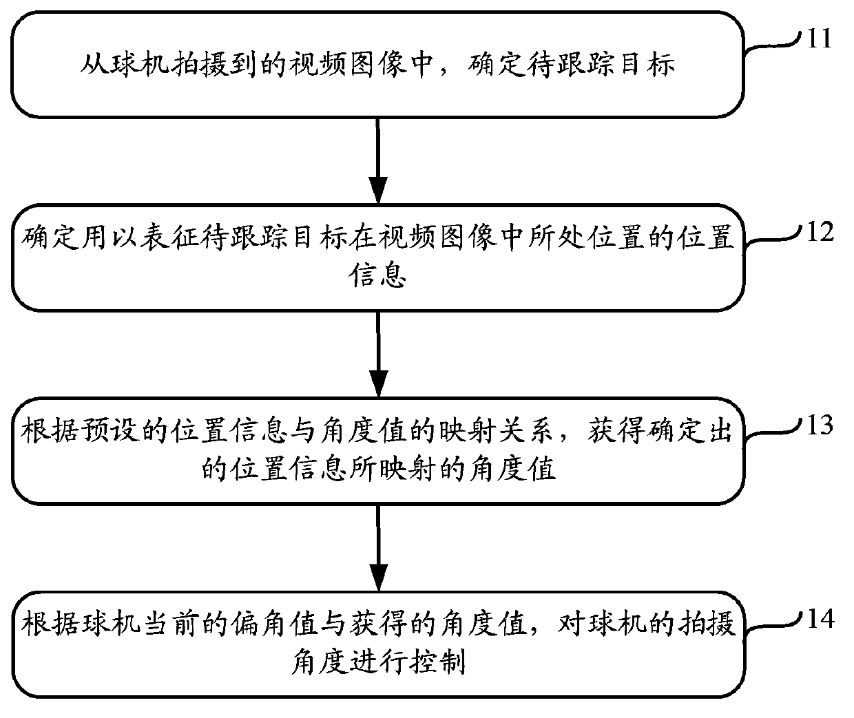
[0046] The specific implementation flow chart of embodiment 1 is as follows Figure 4 shown, including the following steps:

[0047] Step 41, obtain the video image captured by the camera of the dome camera.

[0048] Step 42 , detecting the moving objects contained in the video image, and determining the object to be tracked from the detected moving objects.

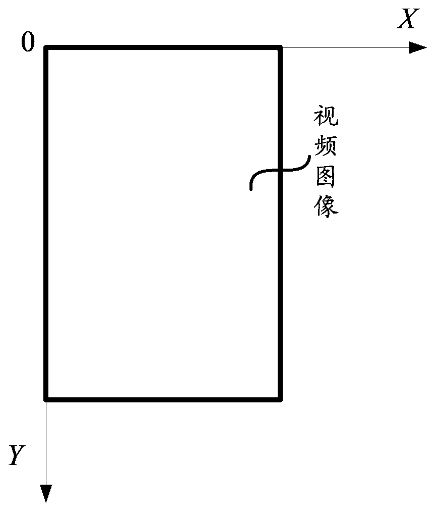
[0049] Step 43, determine the circumscribed rectangular area of ​​the target to be tracked from the video image as the bounding box of the target to be tracked, and determine the coordinate values ​​of the four sides of the bounding box (left f , right f , up f , down f ),Such as Figure 5 shown. in, Figure 5 The coordinate system shown is the image coordinate system described above.

[0050] Step 44, according to the following formula [1], perform calculation of the coordinate value of the center point of the bounding box in the image coordinate system XOY (x of ,y of ) operation.

[0051] ...

Embodiment 2

[0072] The embodiment 2 is based on the embodiment 1, and further improves the control scheme of the ball machine, so as to realize the control of the speed of the ball machine.

[0073]In Embodiment 2, according to the performance of different dome machines, there are two methods to calculate the expected speed of the dome machine rotation, and based on the calculated speed, control the speed of the dome machine rotation. In practical application, you can choose which method to use according to the motor control capability of the ball machine itself. The following describes how to control the rotation speed of the ball machine based on these two methods.

[0074] The speed control process of the dome machine based on the first method includes the following steps:

[0075] Step 1: Estimate the speed of the target to be tracked by using the historical trajectory of the target to be tracked.

[0076] Since some tracking algorithms provided in the prior art are stable, the corr...

Embodiment 3

[0114] Embodiment 3 is based on Embodiment 1, and further improves the control scheme of the dome camera, so as to realize the zoom control of the camera of the dome camera. Specifically, embodiment 3 may include the following steps:

[0115] Step 1: Determine and store the desired multiple of the dome camera, and the declination coordinates of the dome camera corresponding to the desired multiple.

[0116] The specific operation is: control the dome camera to rotate to shoot a specific target, which can be a person or a car. Then, control the magnification of the dome camera to a desired magnification, and confirm that the appearance of the specific target captured by the dome camera at this magnification is clearly visible, and its size accounts for about 1 / 4 to 1 / 2 of the entire video image , keep the shooting angle of the dome camera unchanged, and record the current deflection angle as a w , b w and the current zoom value of the dome camera m w . Among them, the a w...


PUM


Abstract

The invention provides a spherical camera control method and a device thereof, and is used for settling a problem that a spherical camera are not easily controlled for realizing keeping a tracked object to the central position of a video image in prior art. According to the spherical camera control method, a declination angle value of a currently photographed angle of the spherical camera can be objectively reflected, and furthermore an angle value of the object at the position in the video image can be objectively reflected as a basis for controlling the photographing angle of the spherical camera. Therefore relative to a prior art in which a predicated parameter value is adopted as a control basis for the spherical camera, the spherical camera control method according to the solution has higher control accuracy for the spherical camera and can realize a fact that the tracked object is kept in the central position of the video image.

Description

technical field [0001] The invention relates to the technical field of dome cameras, in particular to a dome camera control method and device. Background technique [0002] The dome camera is an intelligent camera front end, its full name is high-speed intelligent dome camera or integrated high-speed smart dome, referred to as fast dome, high-speed dome or dome machine for short. The dome camera is a highly integrated product that integrates the PTZ system (referred to as PTZ), communication system and camera system. Among them, the pan / tilt refers to the rotating part driven by the motor in the ball machine; the communication system refers to the control of the motor and the processing part of the image and signal; the camera system mainly refers to the camera used to obtain video signals, which is installed in On the gimbal, its shooting angle changes with the movement of the gimbal. The CPU and power supply of the dome machine play the role of horizontal connection betw...

Claims


Application Information

Patent Timeline
Patent Type & Authority Applications(China)
IPC IPC(8): H04N5/232
Inventor 周璐王磊潘石柱张兴明傅利泉朱江明吴军吴坚
Owner ZHEJIANG DAHUA TECH CO LTD
Why Eureka
Try Eureka