Interlock tube manufacturing method and manufacturing device therefor

A manufacturing method and a manufacturing device technology, which are applied in the field of the manufacture of interlocking pipes and their manufacturing devices, can solve the problems of springback, rotational loosening, and inability to maintain well, and are easy to achieve high accuracy, excellent work efficiency, and the realization of The effect of work efficiency and economy

Inactive Publication Date: 2014-12-03
SHOWA RASENKAN SEISAKUSHO
View PDF12 Cites 12 Cited by
  • Summary
  • Abstract
  • Description
  • Claims
  • Application Information

AI Technical Summary

Problems solved by technology

[0007] On the other hand, although the interlocking tube with a circular cross-section is wound with a core with a circular cross-section, it cannot be hooked because of its circular shape, and backl

Method used


Image

  • Interlock tube manufacturing method and manufacturing device therefor
  • Interlock tube manufacturing method and manufacturing device therefor
  • Interlock tube manufacturing method and manufacturing device therefor

Examples


Embodiment Construction

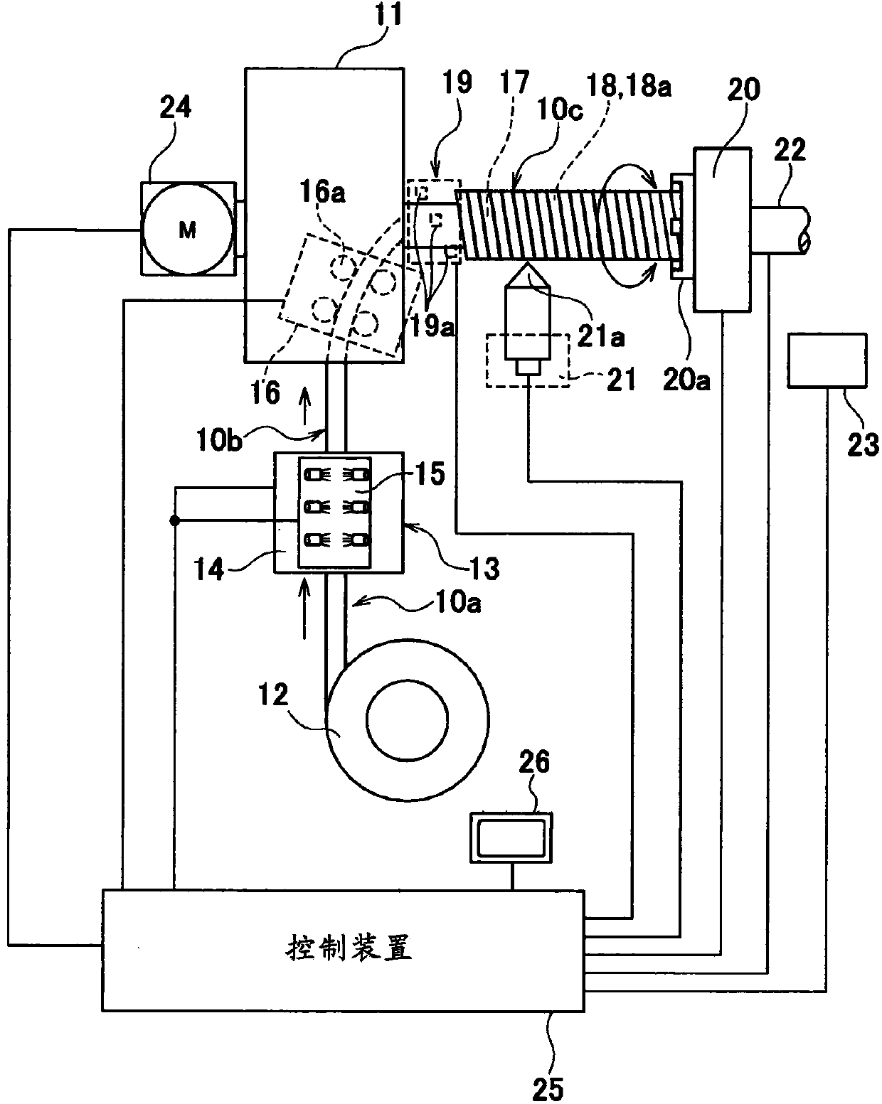
[0038] Hereinafter, embodiments of the present invention will be described with reference to the drawings. figure 1 In order to obtain a semi-finished interlocking pipe 10 used as an exhaust pipe of an automobile, etc., a long flat metal strip 10a having a certain width is formed into a curved metal strip 10b, and at the same time, the forming It is a curved metal strip 10c wound in a spiral shape, and the metal strip 10c is cut into a predetermined length to obtain a semi-finished product of the interlocking pipe 10 . At the beginning, the flat metal strip 10a installed on the uncoiler 12 is pulled out from the uncoiler 12 and simultaneously sent to the pretreatment device 13 including the multi-stage roll forming device 14 and the oiling device 15 .

[0039] The multi-stage roll forming device 14 in the pretreatment device 13 is also as Figure 9 As shown, it is composed of a known multi-stage roll forming apparatus having substantially the same configuration as the conven...


PUM


Abstract

The manufacture of interlock tubes, wherein: tubes, with a circular cross-section or the number of corners in the cross-section being similar to a circle, are easily formed with high precision and without loosening; processability during cutting, etc. is excellent; and the device itself has excellent work efficiency. Interlock tubes are manufactured with excellent work efficiency, etc. by: winding a metal band helically on a winding mandrel, the cross-section of which is circular or a shape in which the number of corners in the cross-section is similar to a circle; installing a fastening chuck on the tip end of the winding mandrel so as to allow free release and fastening; and rotating and synchronizing so as to prevent loosening of the metal band on the basis of commands from a computing/control unit, which integrates the operations of the various units.

Description

technical field [0001] The present invention relates to an interlock that can easily form a tube having a circular cross-section or a pipe with a cross-section close to a circular number of sides with high precision without looseness, excellent processability in cutting, etc., and excellent workability of the device itself. Pipe manufacturing method and manufacturing device thereof. Background technique [0002] In the past, as the exhaust pipe of automobiles and other vehicles, such as Figure 8 Flexible tubing as shown is well known. That is, this flexible tube 1 is a member for preventing vibration from the engine side from being transmitted to downstream components, and an interlocking type flexible tube 2 (hereinafter, referred to as an interlocking tube 2 ) that conducts upstream and downstream components. Tube) is arranged in the center, and bellows 3 with bellows are arranged outside it, and an outer plate 4 is also arranged outside it, and the two ends 3a, 4b of th...

Claims


Application Information

Patent Timeline
IPC IPC(8): B21C37/12F01N13/08F16L11/16
CPCB21C37/12F01N13/1816B21C37/121B21C37/127B21C37/128B21C37/157B23K10/00Y10T29/49927Y10T29/5116B23K2101/06F16L9/02F16L9/22
Inventor 铃木纪房深堀良一
Owner SHOWA RASENKAN SEISAKUSHO
Why Eureka
Try Eureka