Ring taking device for gynecology department

A ring remover and gynecological technology, applied in the field of medical equipment, can solve the problems of low success rate, low work efficiency, deformation and incarceration, etc., and achieve the effect of simple and convenient operation, high success rate and improved work efficiency

Inactive Publication Date: 2014-12-10
卢书美
View PDF6 Cites 1 Cited by
  • Summary
  • Abstract
  • Description
  • Claims
  • Application Information

AI Technical Summary

Problems solved by technology

Clinically, the contraceptive ring needs to be taken out with a ring hook, which is inserted into the uterus through the cervix, and the contraceptive ring is taken out. However, the success rate of this method is low at one time, and it is often necessary to take it several times. The work efficiency is low, and a little careless removal of the ring hook may damage the inner wall of the uterus, which will cause greater pain to the recipient
[0003] In addition, some contraceptive rings are deformed or incarcerated due to a long period of wearing, or due to other reasons, when the ring is removed, it is very painful, and anesthesia is required to relieve the pain, and anesthesia requires special instruments, which makes the entire ring removal process become more difficult. Complicated; according to clinical investigations, most women with rings have different inflammations in the uterus. After removing the rings, anti-inflammatory treatment should be taken in time to prevent further deterioration of inflammation

Method used


Image

  • Ring taking device for gynecology department
  • Ring taking device for gynecology department

Examples


Embodiment

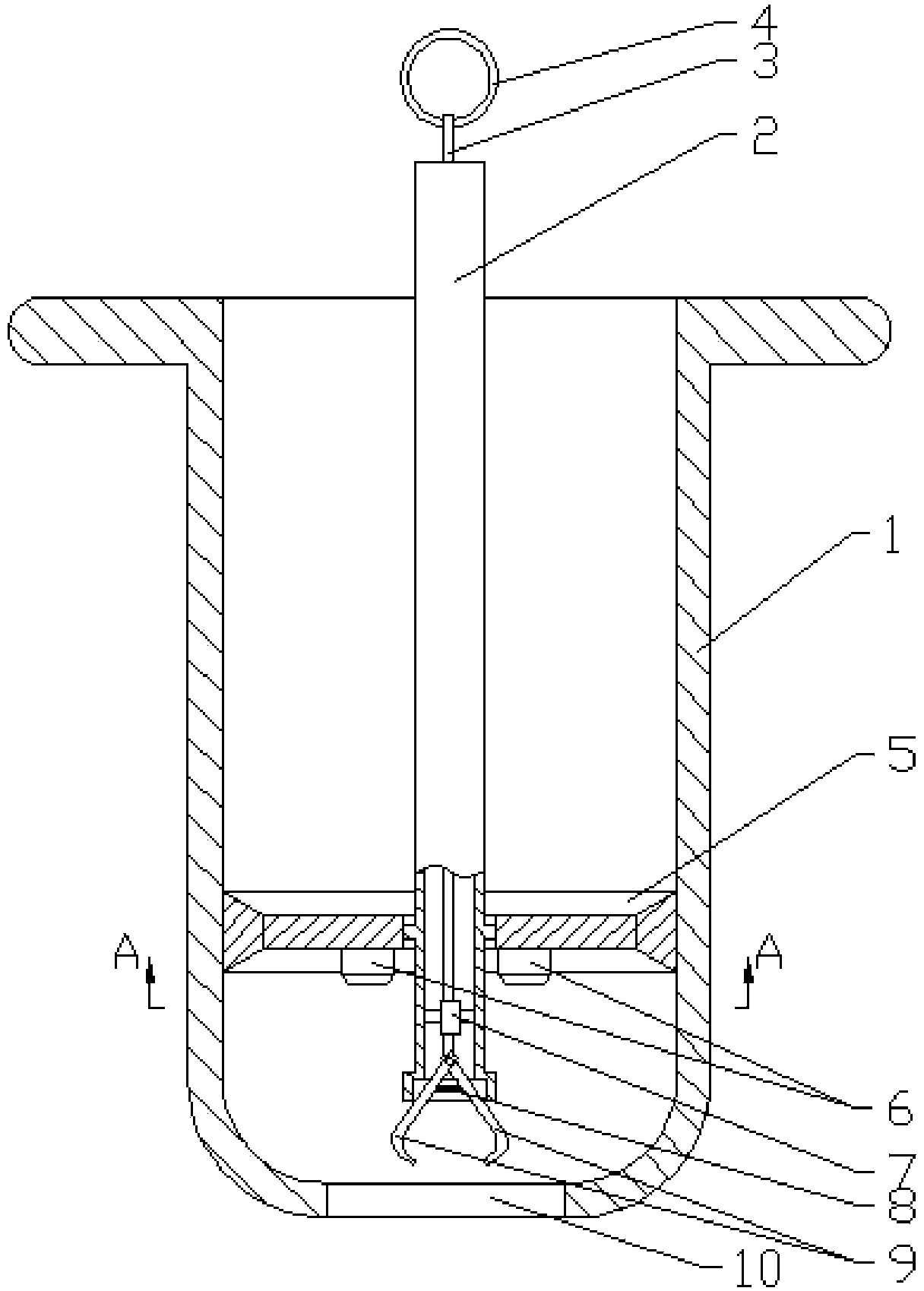
[0025] Example: such as figure 1 and figure 2 As shown, a gynecological ring remover includes a cylindrical housing 1, one end of the housing 1 is provided with a flange, the other end is in a hemispherical structure, and a ring removal hole 10 is provided in the middle. A hollow support rod 2 is provided;

[0026] The support rod 2 is provided with a pull rod 3;

[0027] One end of the pull rod 3 located outside the support rod 2 is provided with a pull ring 4;

[0028] The other end of the pull rod 3 is provided with two ring-taking hooks 9;

[0029] One end of the two ring hooks 9 is hinged to the end of the pull rod 3;

[0030] A compression spring 8 is arranged in the middle of the two ring-taking hooks 9;

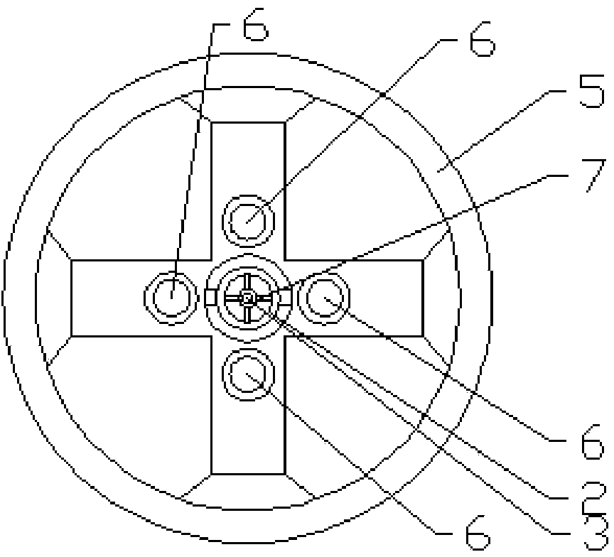
[0031] The inner wall of the support rod 2 is provided with a first support frame 7;

[0032] The pull rod 3 passes through the first support frame 7 .

[0033] The inner wall of the housing 1 is slidably provided with a second support frame 5, and the support...


PUM


Abstract

The invention discloses a ring taking device for a gynecology department. The ring taking device for the gynecology department comprises a barrel-shaped shell, wherein a flange is arranged at one end of the shell; the other end of the shell has a hemispheric structure; a ring taking hole is formed in the middle of the shell; a hollow supporting rod is arranged in the shell; a pulling rod is arranged in the supporting rod; a pulling ring is arranged at one end, which is positioned outside the supporting rod, of the pulling rod; two ring taking hooks are arranged at the other end of the pulling rod; one ends of the two ring taking hooks are hinged to ends of the pulling rod; compression springs are arranged in the middles of the two ring taking hooks; a first supporting rack is arranged on the inner wall of the supporting rod; and the pulling rod penetrates in the first supporting rack. The barrel-shaped shell protects the inner wall of the vagina of a patient from being injured; the ring taking device is provided with the first supporting rack and a second supporting rack, particularly, the supporting rod is movably connected with the second supporting rack, and the ring taking device can move in the left-right direction, so that a ring which is required to be taken can be found out accurately; after the ring taking hooks are aligned with the ring, the pulling ring is pulled, and the ring can be taken down from the cervix uteri of the user; the ring taking device is easy and convenient to operate; the one-step success rate is high; and the work efficiency is greatly improved.

Description

technical field [0001] The invention relates to a medical device, in particular to a gynecological ring remover. Background technique [0002] At present, the contraceptive methods for married women of childbearing age in my country mainly include instrumental contraception, drug contraception, and natural contraception, among which the intrauterine device (IUD) is a relatively safe, convenient and extensive contraceptive method. The intrauterine device is a ring (also known as contraceptive ring, birth control ring) made of stainless steel, plastic, or silicone rubber. Its role is mainly to resist fertilization and prevent the implantation of fertilized eggs. , so as to achieve the purpose of contraception. It is effective for a long time after being placed, and can be taken out when pregnancy is required without affecting fertility. Clinically, the contraceptive ring needs to be taken out with a ring hook, which is inserted into the uterus through the cervix, and the con...

Claims


Application Information

Patent Timeline
Patent Type & Authority Applications(China)
IPC IPC(8): A61F6/18
Inventor 曹双元郭艳张燕
Owner 卢书美
Why Eureka
Try Eureka