Parallel mechanism arm

A manipulator and parallel technology, applied in the field of manipulators, can solve the problems of the mechanism occupying a large working space, deteriorating the dynamic performance of the system, increasing the inertia of the system motion, etc., to achieve the effect of improving production efficiency, large space utilization, and reducing interference

Inactive Publication Date: 2014-12-10
SHENZHEN DAYUCNC TECH
View PDF8 Cites 9 Cited by
  • Summary
  • Abstract
  • Description
  • Claims
  • Application Information

AI Technical Summary

Problems solved by technology

[0003] (1) The bearing capacity is low, the stiffness is small, and the structure is not stable enough;
[0004] (2) The error of the end effector is accumulated and amplified by the errors of each joint, so the error is large and the precision is low;
[0005] (3) Most of the driving motors and servo systems are placed on the moving arms, which increases the motion inertia of the system and deteriorates the dynamic performance of the system;
[0006] (4) The mechanism occupies a large working space and is easy to interfere with the working platform

Method used


Image

  • Parallel mechanism arm
  • Parallel mechanism arm
  • Parallel mechanism arm

Examples


Embodiment Construction

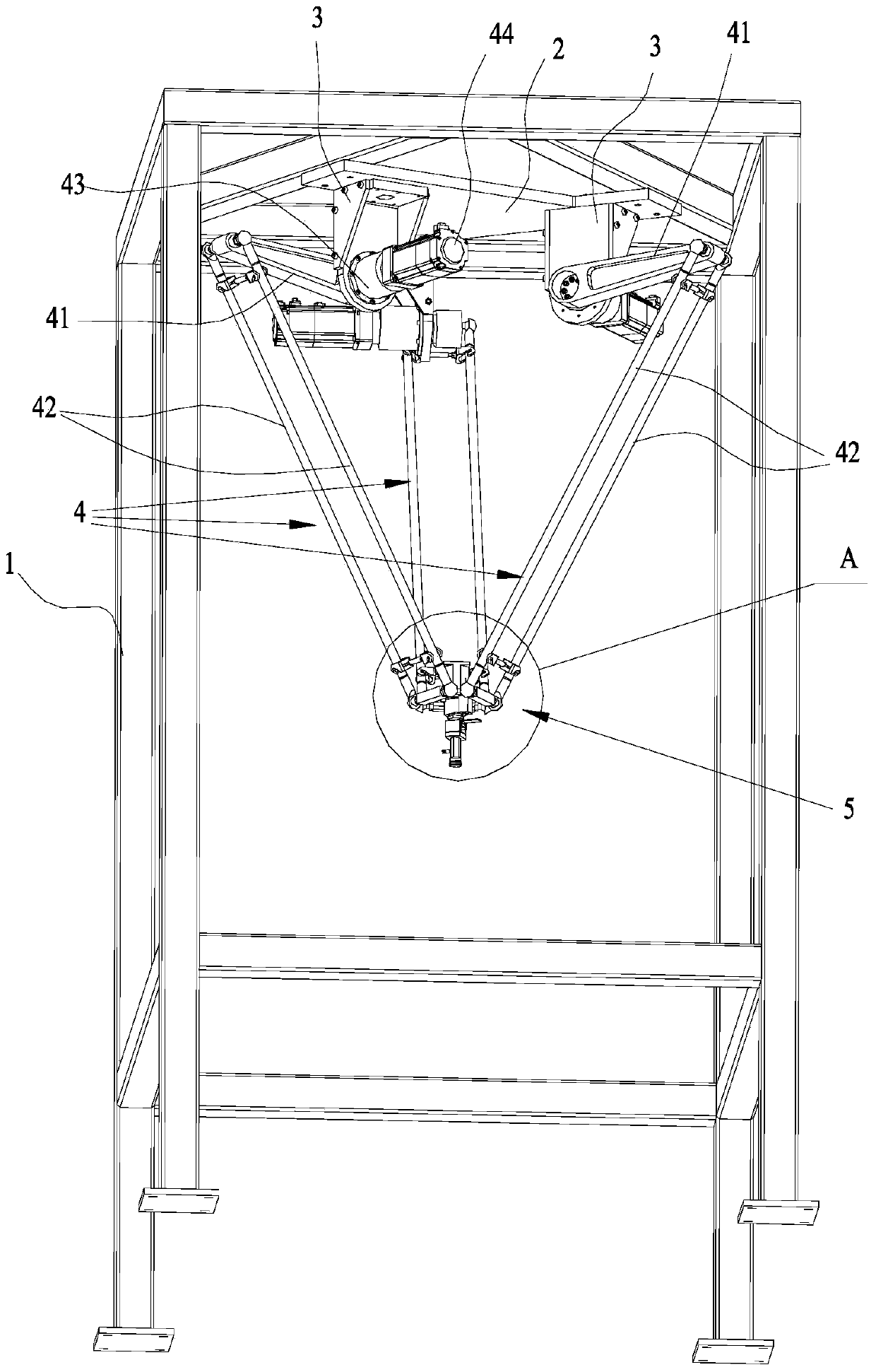
[0027] Such as figure 1 The shown parallel manipulator comprises a fixed frame 1, a horizontal plate 2, a plurality of suspension frames 3, a plurality of transmission mechanisms 4 and an adsorption device 5, the horizontal plate 2 is fixed on the top of the fixed frame 1, each suspension frame 3 One end is fixed to the horizontal plate 2 respectively, the other end of each suspension frame 3 extends vertically downward, the adsorption device 5 is located below the suspension frame 3, and each suspension frame 3 is distributed symmetrically with the vertical line axis where the center of the horizontal plate 2 is located; Each transmission mechanism 4 includes a master arm 41, a slave arm 42, a reducer 43 and a servo motor 44, the reducer 43 is fixedly connected to the lower end of the suspension frame 3, and the output shaft of the servo motor 44 is connected to the master arm 41 through the reducer 43 One end of the main arm 41 is hinged with one end of the slave arm 42, and...


PUM


Abstract

The invention discloses a parallel mechanical arm. The parallel mechanism arm comprises a fixing frame, a horizontal plate, a plurality of overhung frames, a plurality of transmission mechanisms and a suction device. The horizontal plate is fixed to the top of the fixing frame. One end of each overhung frame is fixedly connected with the horizontal plate. The other end of each overhung frame downwards extends out vertically. The suction device is located below the overhung frames. The overhung frames are in axis symmetry about the vertical line where the center of the horizontal plate is located. Each transmission mechanism comprises a driving arm, a driven arm, a speed reducer and a servo motor. The speed reducer is fixedly connected with the lower end of the corresponding overhung frame. An output shaft of each servo motor is in butt joint with one end of the corresponding driving arm through the speed reducer. The other end of each driving frame is hinged to one end of the corresponding driven arm. The other end of each driven arm is hinged to the suction device. The parallel mechanical arm is small in error, high in space utilization rate and reliable in use.

Description

technical field [0001] The invention relates to a manipulator, in particular to a parallel manipulator. Background technique [0002] In traditional factories, a large number of repetitive tasks such as sorting, picking, and packing are generally done manually, which has problems such as high labor intensity, time-consuming, boring, easy to cause pollution, and will increase the cost of the enterprise. Therefore, in these fields, manipulators are required to perform high-speed, medium and short-distance grabbing, handling and placement of light and small materials. In industrial production, tandem manipulators are generally used, and tandem manipulators have the following disadvantages: [0003] (1) The bearing capacity is low, the stiffness is small, and the structure is not stable enough; [0004] (2) The error of the end effector is accumulated and amplified by the errors of each joint, so the error is large and the precision is low; [0005] (3) Most of the driving mo...

Claims


Application Information

Patent Timeline
Patent Type & Authority Applications(China)
IPC IPC(8): B25J9/00B25J19/00
CPCB25J9/0051
Inventor 雷万春张钦炎蒋幸福张栩俊
Owner SHENZHEN DAYUCNC TECH
Why Eureka
Try Eureka