A portable mobile robot

A mobile robot and portable technology, applied in the field of mobile robots, can solve the problems of poor obstacle surmounting ability and insufficient load capacity, and achieve the effect of strong obstacle surmounting ability, convenient transformation and enhancement of obstacle surmounting ability.

Active Publication Date: 2016-06-15
SHENYANG INST OF AUTOMATION - CHINESE ACAD OF SCI
View PDF5 Cites 0 Cited by
  • Summary
  • Abstract
  • Description
  • Claims
  • Application Information

AI Technical Summary

Problems solved by technology

Portable mobile robots with small size and light weight have many advantages in application, but they also have limitations such as poor obstacle-surmounting ability and insufficient load capacity.

Method used


Image

  • A portable mobile robot
  • A portable mobile robot
  • A portable mobile robot

Examples


Embodiment 1

[0026] Embodiment 1 (Mode 1)

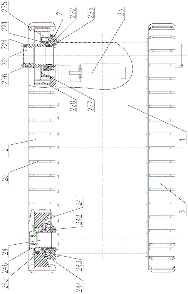
[0027] Such as figure 1 As shown, the portable mobile robot of this embodiment includes a box body 1, a left walking mechanism 2, and a right walking mechanism 3, wherein the left walking mechanism 2 includes a left side plate 21, a front wheel assembly 22, a left front wheel drive Assembly 23 , rear wheel assembly 24 and drive track 25 . The left side side plate 21 is an important part of the left side running gear 2, and is used to install the front wheel assembly 22, the left front wheel drive assembly 23 and the rear wheel assembly 24, and the left front wheel drive assembly 23 and the front wheel assembly 22 are respectively located at The inside and outside of the left side plate 21 front; Mounted with end gears. Front wheel assembly 22 comprises bull gear 221, cross roller bearing 222 for drive wheel, drive shaft 223, drive wheel bearing end cover 225, spline shaft 226 for drive wheel, seal cover 227 and drive wheel 228, and drive shaft...

Embodiment 2

[0034] Embodiment two (mode two)

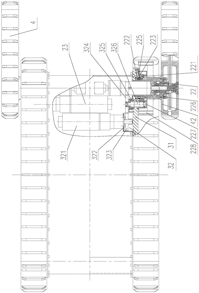
[0035] The difference between this embodiment and Embodiment 1 is that the outer sides of the drive wheel spline shafts 226 in the front wheel assemblies 22 on the left and right sides are not bolted to the drive wheel end cover 224, but are respectively connected to small arm assemblies with the same structure. 4. Such as figure 2 As shown, the small arm assembly 4 includes a small arm transmission shaft 41, a small arm driving wheel 42, a small arm 43, a small arm support wheel 44, a small arm track 45 and a small arm drive assembly 46, and two small arm drive assemblies on the left and right sides The fixed ends of 46 are respectively bolted to the front of the left side plate 21 and the right side plate 31, one end of the small arm drive assembly 46 is accommodated in the box body 1, and the other end (output end) is used by the drive shaft 223 and the drive wheel. The spline shaft 226 passes through the middle and is keyed to the smal...

Embodiment 3

[0039] Embodiment three (mode three)

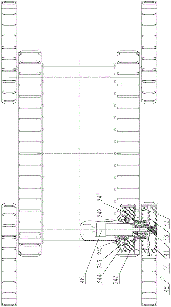
[0040] The difference between this embodiment and the second embodiment is that the outer sides of the rear wheels 241 in the left and right rear wheel assemblies 24 are not bolted to the rear wheel end caps 246 , but connected to the small arm assemblies 4 with the same structure. Such as image 3 As shown, the fixed ends of the two forearm drive assemblies 46 located at the front on the left and right sides are respectively bolted to the front of the left side plate 21 and the right side plate 31, and the two forearm drive assemblies 46 located at the rear on the left and right sides The fixed ends are bolted to the support shafts 242 in the rear wheel assemblies 24 on the left and right sides. One end of the two forearm drive assemblies 46 at the front is housed in the box body 1, and the other end (output end) passes through the middle of the drive shaft 223 and the spline shaft 226 for the drive wheel, and is keyed to the forearm tr...


PUM


Abstract

The invention belongs to the field of mobile robots, in particular to a portable mobile robot, which includes a box body and left and right walking mechanisms. The left walking mechanism and the right walking mechanism are symmetrically arranged on both sides of the box body. Arranged in the front or front and back of the left and right side walking gears according to needs; the present invention has three modes: mode one includes box body, left side running gear and right side running gear; mode two includes box body, left side running gear, The right walking mechanism and two small arm components, that is, the small arm components are respectively arranged in the front of the left side of the left walking mechanism and the front of the right side of the right walking mechanism; Mode 3 includes the box body, the left walking mechanism, and the right walking mechanism Mechanism and four forearm assemblies, promptly configure forearm assemblies respectively before and after the left side of the left traveling mechanism and the front and rear of the right traveling mechanism right side. The invention has the characteristics of small size, light weight, strong obstacle-surmounting ability and load capacity, and is suitable for fields such as reconnaissance and anti-terrorism.

Description

technical field [0001] The invention belongs to the field of mobile robots, in particular to a portable mobile robot. Background technique [0002] With the rapid development of robot technology, mobile robots have been widely used in the fields of investigation and anti-terrorism. Portable mobile robots with small size and light weight have many advantages in applications, but they also have limitations such as poor obstacle-surmounting ability and insufficient load capacity. Therefore, it is very necessary to develop a portable mobile robot with strong obstacle-surmounting ability and load capacity. Contents of the invention [0003] The object of the present invention is to provide a portable mobile robot. The portable mobile robot has multiple modes, which can solve the contradiction among the mobile robot's ability to overcome obstacles, load capacity and portability. [0004] The purpose of the present invention is achieved through the following technical solution...

Claims


Application Information

Patent Timeline
Patent Type & Authority Patents(China)
IPC IPC(8): B62D55/065
Inventor 吴镇炜赵忆文卜春光高英丽
Owner SHENYANG INST OF AUTOMATION - CHINESE ACAD OF SCI
Why Eureka
Try Eureka