Energy-saving electric spindle assembly

A technology of electric ingots and components, applied in textiles and papermaking, etc., can solve the problem of large energy consumption of ingots

Inactive Publication Date: 2014-12-10
YICHANG JINGWEI TEXTILE MACHINERY
View PDF10 Cites 1 Cited by
  • Summary
  • Abstract
  • Description
  • Claims
  • Application Information

AI Technical Summary

Problems solved by technology

[0005] To sum up, in the usual industrial yarn twisting production, the spindle consumes a lot

Method used


Image

  • Energy-saving electric spindle assembly

Examples


Embodiment 1

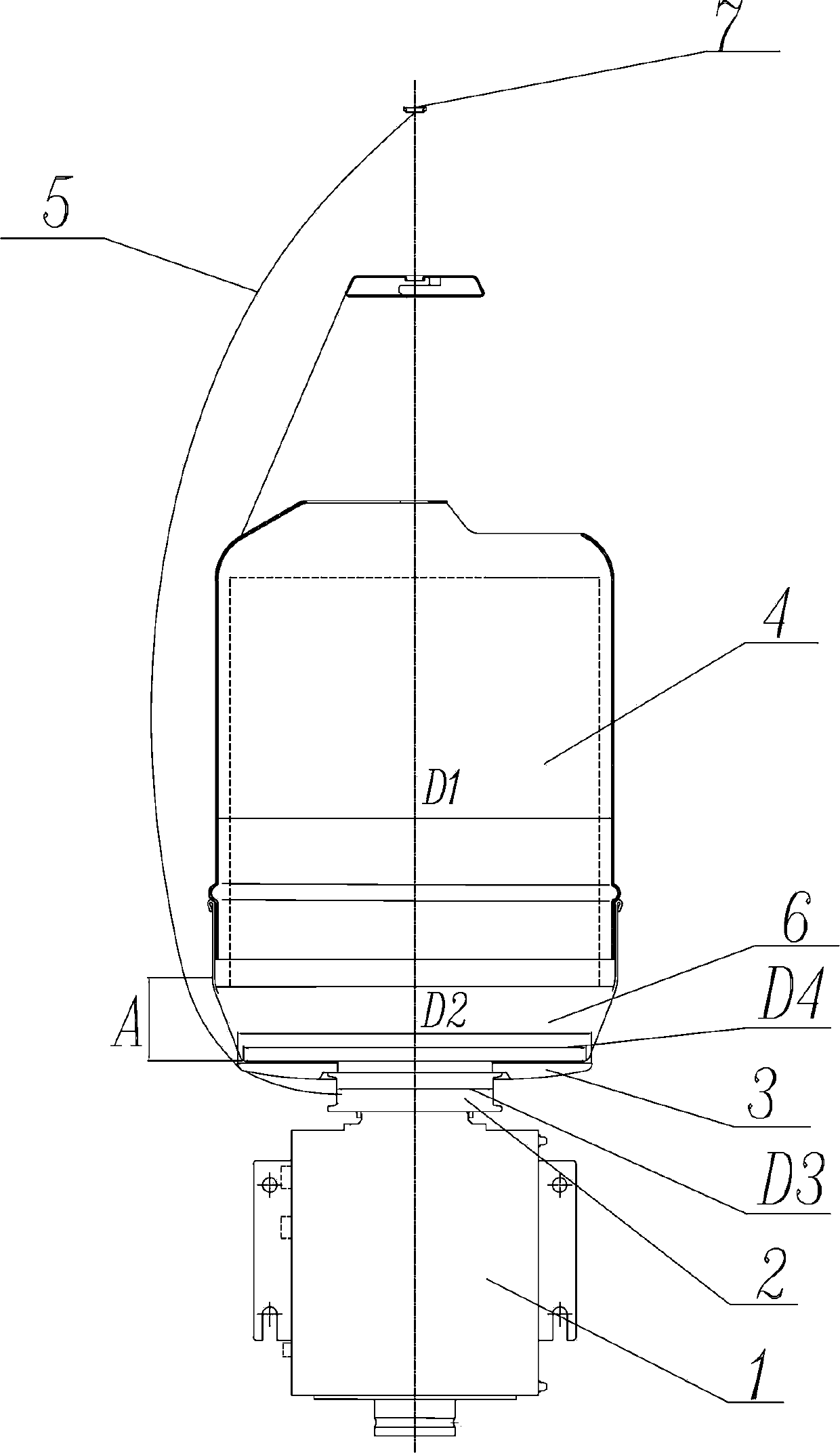
[0023] Such as figure 1 Among them, an energy-saving electric spindle assembly, including: a motor 1, a rotatable yarn storage disc 2 directly connected to the output shaft of the motor, a rotatable twisting disc 3 connected to the yarn storage disc 2, and is arranged on the twisting disc 2 The upper and fixed ingot can 4, the ingot can 4 is used to accommodate the feeding package;

[0024] For industrial yarn with twisting feeding package diameter ≤ φ230mm and yarn fineness range of 840dtex-2600dtex, the minimum diameter D4 of the bottom of the ingot pot is φ210mm to φ215mm, the maximum outer diameter D1 of the ingot pot is φ245mm to φ250mm, the diameter of the twisting disc D2 is φ220mm to φ225mm, and the diameter of the yarn storage disc D3 is φ80mm to φ85mm.

[0025] During the operation of the spindle, the yarn is guided from the yarn storage disc 2 to the twisting disc 3, and then from the twisting disc 3 to the yarn guide 7 above the spindle pot 4. When the spindle spe...

Embodiment 2

[0029] On the basis of Example 1, the minimum diameter D4 at the bottom of the ingot pot is φ210mm, the maximum outer diameter D1 of the ingot pot is φ245mm, the diameter D2 of the twisting disc is φ220mm, and the diameter D3 of the yarn storage disc is φ80mm. When the spindle speed is 8000-9500rpm, compared with the prior art, the energy required to drive the spindle to work is reduced by 13% compared with the known technical solution.

Embodiment 3

[0031] On the basis of Example 1, the minimum diameter D4 at the bottom of the ingot pot is φ215mm, the maximum outer diameter D1 of the ingot pot is φ250mm, the diameter D2 of the twisting disc is φ225mm, and the diameter D3 of the yarn storage disc is φ85mm. When the spindle speed is 8000-9500rpm, compared with the prior art, the energy required to drive the spindle to work is reduced by 10% compared with the known technical solution.


PUM

PropertyMeasurementUnit
Minimum diameteraaaaaaaaaa
Outer diameteraaaaaaaaaa
Diameteraaaaaaaaaa

Abstract

Disclosed is an energy-saving electric spindle assembly. The energy-saving electric spindle assembly comprises a motor, a rotatable yarn storage tray which is directly connected with a motor output shaft, a rotatable twisting tray which is connected with the yarn storage tray, and a spindle tank which is arranged above the twisting tray and is stationary. The spindle tank is used for containing a feeding package. The minimum diameter of the bottom of the spindle tank is phi 210 mm to phi 215 mm, the maximum outer diameter of the spindle tank is phi 245 mm to phi 250 mm, the diameter of the twisting tray is phi 220 mm to phi 225 mm, and the diameter of the yarn storage tray is phi 80 mm to phi 85 mm. According to the energy-saving electric spindle assembly, the size, the structure and the geometrical shape of the spindle tank, the twisting tray and the yarn storage tray are optimized and designed, the diameter of free ballooning which is generated by the way that yarns rotate along with a spindle is reduced, the quality of twisted yarns is guaranteed, and meanwhile energy needed by a twisting frame for driving the spindle to work is reduced. According to the energy-saving electric spindle assembly, for a feeding yarn conventional variety with the yarn fineness range being 840 dtex-2600 dtex and the package diameter being smaller than or equal to 230 mm, the direct twisting or two-for-one twisting spindle assembly with the above characteristics is compared with the structure in the prior art, and the purpose for saving energy by 10%-13% is achieved.

Description

technical field [0001] The invention relates to a direct-twisting or two-for-one-twisting spindle assembly used in a twisting machine in the field of textile machinery, in particular to a direct-twisting or two-for-one-twisting electric spindle assembly. Background technique [0002] Existing direct-twist or two-for-one twist spindles usually have a stationary spindle pot that accommodates the feed yarn package and a rotatably working spindle that includes a yarn storage disc and a twisting disc. When the yarn exported from the yarn storage disk of the spindle is guided upwards to the yarn guide above the spindle pot through the twisting disk, the yarn will generate an air circle around the spindle pot as the spindle rotates, the energy required for the rotation of the spindle itself and the yarn The energy consumed by the air circle generated by thread twisting to overcome air resistance is the driving energy required for the spindle to work, which is the main component of ...

Claims


Application Information

Patent Timeline
IPC IPC(8): D01H7/74D01H7/78D01H7/86
Inventor 杨华明潘松许金甲冉文杨华年
Owner YICHANG JINGWEI TEXTILE MACHINERY
Why Eureka
Try Eureka