Steel box girder erection method applied to steel and concrete hybrid girder cable-stayed bridge

A technology of steel box girders and concrete box girders, which is applied in cable-stayed bridges, bridge construction, erection/assembly of bridges, etc., and can solve problems such as inability to meet the erection requirements of ground transportation, limited spans of temporary buttresses, and the need for ground transportation channels, etc. , to achieve the effect of promoting the development of construction technology, solving construction technical problems and reducing construction costs

Inactive Publication Date: 2014-12-10
THE SECOND CONSTR OF CTCE GROUP +2
View PDF4 Cites 31 Cited by
  • Summary
  • Abstract
  • Description
  • Claims
  • Application Information

AI Technical Summary

Problems solved by technology

The other is the longitudinal jacking method, which is mainly characterized by setting a jacking construction platform on one side (or both sides) of the bridge, setting up temporary buttresses, slideways, guide beams, etc., relying on the jacking device, single-point or multi-point jacking Push the girder body into place gradually along the longitudinal axis of the bridge, install the stay cables and form the bridge; this method needs to set up a large j

Method used


Image

  • Steel box girder erection method applied to steel and concrete hybrid girder cable-stayed bridge
  • Steel box girder erection method applied to steel and concrete hybrid girder cable-stayed bridge
  • Steel box girder erection method applied to steel and concrete hybrid girder cable-stayed bridge

Examples


Embodiment Construction

[0030] The present invention is applied to engineering example, provides a kind of new steel box girder erection method, in conjunction with accompanying drawing, specific implementation of the present invention is described as follows:

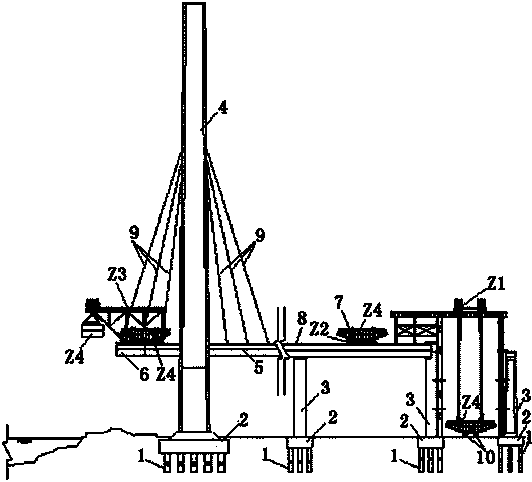
[0031] A. Construction of pile foundation (1), cap (2), pier body (3), cable tower (4), side-span concrete box girder (5) and steel-concrete combination section (6) is carried out in sequence, and the concrete box girder ( 5) The construction is completed with cast-in-place supports;

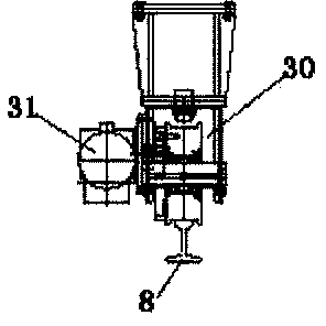
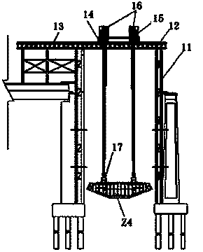
[0032] B. At the end of the bridge, use the foundation of the constructed cap (2) to install the girder door frame (Z1) that can lift the steel box girder (Z4) to the concrete beam surface of the side span in sections, and install the first to third pairs one by one during the period Stay cables (9) are tensioned symmetrically in pairs in sequence;

[0033] C. Assemble and anchor the cantilever bridge erecting machine (Z3) near the mid-span end of the concrete...


PUM


Abstract

The invention discloses a steel box girder erection method which is applied to a steel and concrete hybrid girder cable-stayed bridge. Side-span concrete girders are constructed first, and middle-span steel box girders are installed in a segmented mode. The segments of the steel box girders are lifted to a girder transport cart on the constructed side-span girder face through a bridge tail girder lifting gantry, the steel box girders are transported into a cantilever bridge girder erection machine along rails on the girder face through the cart, and then the steel box girders are hoisted, transferred forward, turned, transferred backward and installed through the cantilever bridge girder erection machine. The constructed side-span concrete girders serve as the middle-span steel box girder transportation channel for transporting girders on girders, the steel box girder lifting, transporting and erecting process is not limited by ground construction, and navigation is not affected; the problems of construction environment constraints are solved, and multiple construction devices involved in steel box girder erection are innovatively designed, developed and successfully applied. According to on-site practice, all links are compact and controllable in terms of construction time, the steel box girder erection method is safe, reliable and high in applicability, the defects of a traditional construction method are compensated for, and development of the steel box girder erection construction technology is promoted.

Description

technical field [0001] The invention relates to the field of steel box girder erection, in particular to a steel box girder erection method suitable for steel-concrete mixed girder cable-stayed bridges. Background technique [0002] There are generally two types of conventional erection of steel box girders of cable-stayed bridges: one is the cantilever assembly method. The surface crane is lifted section by section and erected into a bridge; this method requires a transportation channel at the bridge location and will affect the existing traffic under the bridge for a long time. The other is the longitudinal jacking method, which is mainly characterized by setting a jacking construction platform on one side (or both sides) of the bridge, setting up temporary buttresses, slideways, guide beams, etc., relying on the jacking device, single-point or multi-point jacking Push the girder body into place gradually along the longitudinal axis of the bridge, install the stay cables ...

Claims


Application Information

Patent Timeline
IPC IPC(8): E01D21/00E01D11/04
Inventor 李世铭胡晓东伍军
Owner THE SECOND CONSTR OF CTCE GROUP
Why Eureka
Try Eureka