
LED (light emitting diode) ceiling lamp

A technology of LED ceiling lamps and LED light sources, which is applied in cooling/heating devices of lighting devices, lighting and heating equipment, point light sources, etc. High utilization rate, simple and beautiful appearance, long service life

Inactive Publication Date: 2014-12-10
曹建敏
View PDF0 Cites 0 Cited by
  • Summary
  • Abstract
  • Description
  • Claims
  • Application Information

AI Technical Summary

Problems solved by technology

The light source of existing ceiling lamps generally adopts ordinary fluorescent tubes, which have mediocre luminous effects, high power consumption, short service life, and the internal fluorescent powder is easy to cause harm to the environment, which does not conform to the concept of energy saving and environmental protection
Moreover, parts such as the ballast or the driving device of the existing ceiling lamp are generally arranged between the front of the chassis of the ceiling lamp and the light-transmitting cover, or are exposed on the back of the chassis, and the driving device is arranged on the front of the chassis and the transparent cover. Between the mask, it is easy to block the light, resulting in a dark area of ​​light emission, a narrow light emission range, and poor light emission effect. When the driving device is installed on the back of the chassis, it will be exposed, which affects the appearance of the appearance.

Method used


Image

  • LED (light emitting diode) ceiling lamp
  • LED (light emitting diode) ceiling lamp
  • LED (light emitting diode) ceiling lamp

Examples


Embodiment Construction

[0021] It should be understood that the specific embodiments described here are only used to explain the present invention, not to limit the present invention.

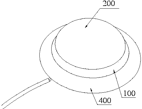
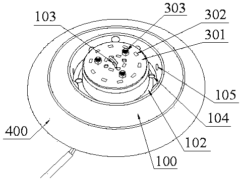
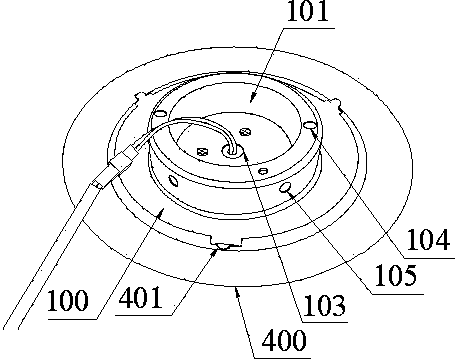
[0022] refer to Figure 1 to Figure 3 , an embodiment of an LED ceiling lamp of the present invention is proposed, including a chassis 100, an LED light source assembly disposed on the chassis 100, a driving device electrically connected to the LED light source assembly, and a light-transmitting cover disposed on the LED light source assembly 200.

[0023] A cavity 101 extending from the center of the back of the chassis 100 can accommodate the drive device and wires. The drive device and wires are accommodated inside the cavity 101 so that they will not be exposed. After the entire lamp is installed, it cannot be seen from the outside. The driving device and wires have a simple and beautiful appearance.

[0024] An LED light source assembly is installed and fixed on the front of the concave cavity 101 , and the LED...


PUM


Abstract

The invention discloses an LED (light emitting diode) ceiling lamp. The LED ceiling lamp comprises a base plate, an LED light source subassembly, a driving device and a light transmitting cover, wherein the center of the back surface of the base plate extends to form a cavity; and the driving device and a wire can be accommodated in the cavity and are not exposed, so that the light ceiling lamp is simple and attractive in appearance. The LED light source subassembly is fixedly arranged on the front surface of the cavity. Compared with the traditional fluorescent tube, the LED ceiling lamp is high in lighting effect, low in power consumption and long in service life, and is energy-saving and environment-friendly. An annular groove is formed in the front surface of the base plate and surrounds the cavity; an annular inclined plane which is inclined outwards is arranged on the front surface of the base plate; the height of the cavity is greater than that of the outer edge of the annular groove by 0.2 centimeter to 0.5 centimeter, light emitted from the LED ceiling lamp cannot be shielded by the annular groove, and dark zones do not exist. The LED ceiling lamp is wide in light emitting range, high in light using rate and high in lighting effect.

Description

technical field [0001] The invention relates to a ceiling lamp, in particular to an LED ceiling lamp. Background technique [0002] Ceiling lamp is a kind of light fixture. As the name suggests, it is called ceiling light because the top of the light fixture is relatively flat and the bottom is completely attached to the roof when installed. Ceiling lamps are widely used in various occasions such as homes, offices, and entertainment venues. The light source of existing ceiling lamps generally adopts ordinary fluorescent tubes, which have mediocre luminous effects, high power consumption, and short service life, and the internal fluorescent powder is likely to cause harm to the environment, which does not conform to the concept of energy saving and environmental protection. Moreover, parts such as the ballast or the driving device of the existing ceiling lamp are generally arranged between the front of the chassis of the ceiling lamp and the light-transmitting cover, or are ...

Claims


Application Information

Patent Timeline
Patent Type & Authority Applications(China)
IPC IPC(8): F21S8/04F21V23/00F21V23/06F21V17/10F21V17/12F21V29/00F21Y101/02
Inventor 曹建敏
Owner 曹建敏
Learn More