Mirror displacement measurement method based on feature pattern reflecting

A displacement measurement and feature pattern technology, applied in the field of mirror displacement measurement and testing, to achieve the effects of high sensitivity, simple structure and large measurement dynamic range

Active Publication Date: 2014-12-10
INST OF OPTICS & ELECTRONICS - CHINESE ACAD OF SCI
View PDF4 Cites 9 Cited by
  • Summary
  • Abstract
  • Description
  • Claims
  • Application Information

AI Technical Summary

Problems solved by technology

However, there has been no report on the use of structured light methods to measure the displacement of mirrors.

Method used


Image

  • Mirror displacement measurement method based on feature pattern reflecting
  • Mirror displacement measurement method based on feature pattern reflecting
  • Mirror displacement measurement method based on feature pattern reflecting

Examples


Embodiment Construction

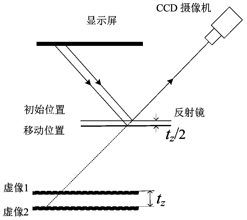
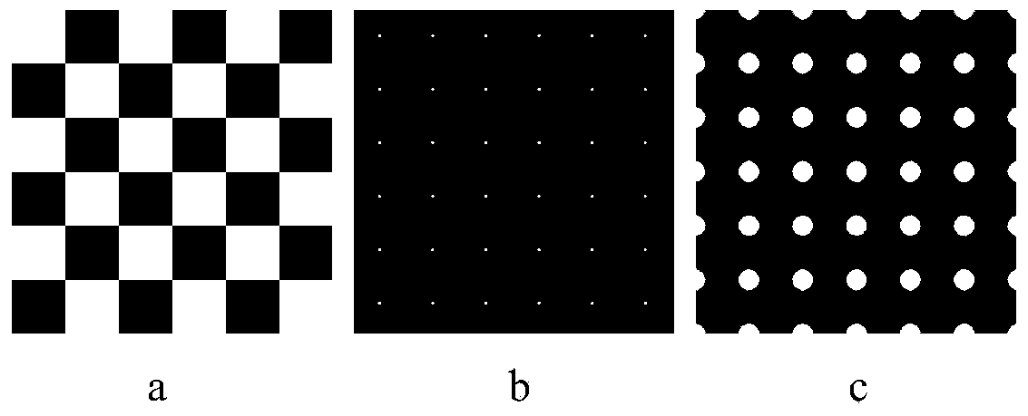
[0018] Such as figure 1 As shown, the system includes a CCD camera, a display screen and a computer. The characteristic patterns generated by the computer are displayed on the display screen, and are captured and recorded by the CCD camera after being reflected by the measured object or the mirror fixed on the object. That is, the CCD shoots and records the virtual image formed by the reflector on the display screen. When the mirror moves, the virtual image also moves relative to the camera. By calibrating the extrinsic parameters of the camera, the moving distance of the virtual image relative to the camera before and after the movement of the mirror can be calculated. According to the law of light reflection, half of this distance is the moving distance of the mirror. The following takes the checkerboard feature pattern displayed on the display as an example for illustration.

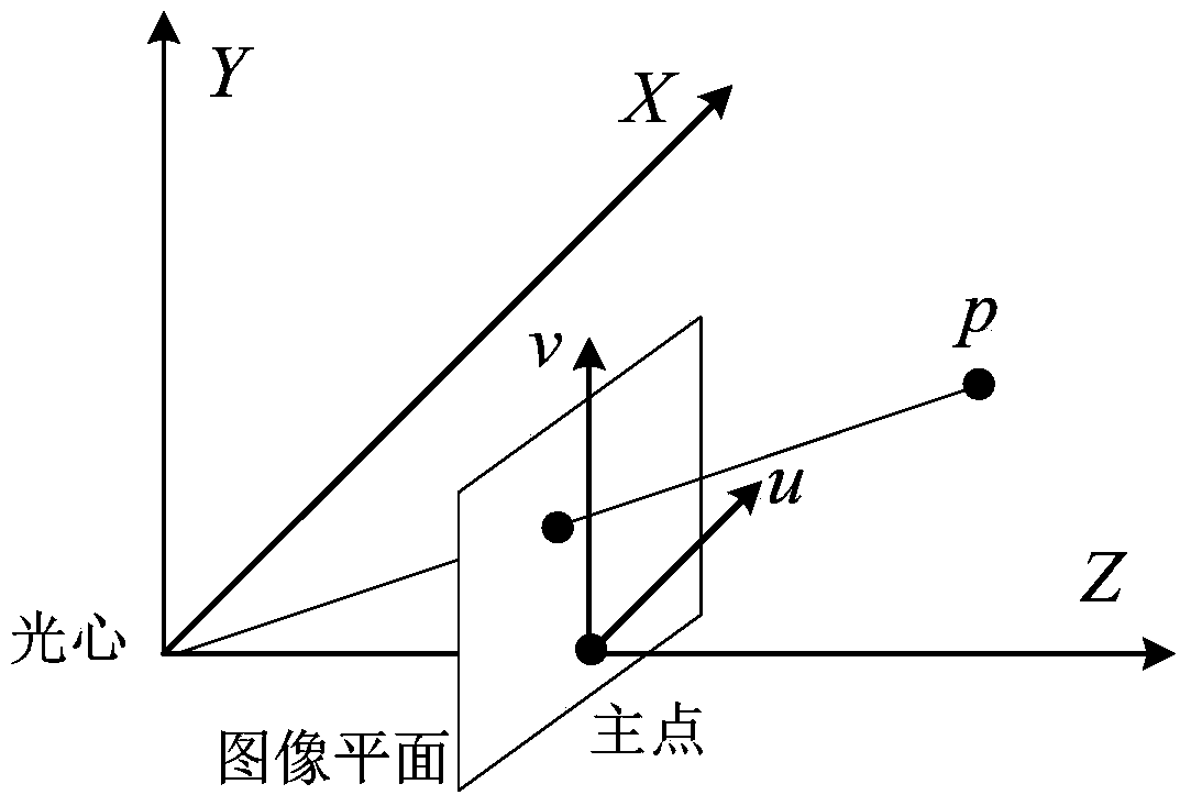
[0019] Firstly, the internal parameters of the camera are obtained through standardization. C...


PUM


Abstract

The invention discloses a mirror displacement measurement method based on feature pattern reflecting. A feature pattern is displayed on a display screen and projected to a mirror, and after reflected, the feature pattern is photographed with a CCD (charge coupled device) camera. The CCD camera photographs and records the reflected feature pattern, namely the CCD camera photographs and records a virtual image formed by the mirror on the display screen. When the mirror moves, the virtual image photographed by the CCD camera moves meanwhile. Inner and outer parameters of the CCD camera can be calibrated to obtain a displacement distance of the virtual image formed by movement of the mirror; according to the law of light reflection, the displacement distance of the mirror is half of that of the virtual image, and displacement of the mirror is obtained.

Description

technical field [0001] The invention relates to an optical displacement measurement technology, in particular to a mirror displacement measurement test method. technical background [0002] Displacement measurement plays an increasingly important role in many measurement fields such as optical precision instruments and material measurement. To measure displacement, contact measurement method and non-contact measurement method can be used. Traditional contact measurement methods include dial indicators, three-coordinate measuring machines, linear gratings, laser trackers, etc. Non-contact measurement methods mainly use laser ranging or measuring triangle principles, such as laser femtosecond method, laser measurement Tachymeter etc. These measurement methods have their own characteristics and limitations, and are applicable to different measurement fields. In optical assembly, it is usually necessary to measure the displacement of the mirror. Usually the surface of this k...

Claims


Application Information

Patent Timeline
Patent Type & Authority Applications(China)
IPC IPC(8): G01B11/02G06F19/00
Inventor 赵文川李璐璐范斌
Owner INST OF OPTICS & ELECTRONICS - CHINESE ACAD OF SCI
Why Eureka
Try Eureka