
Positioning detector

A technology of a detector and a positioning part, which is applied in the field of satellite positioning, can solve the problem that a positioning detector cannot accurately determine the positioning accuracy, and achieves the effects of simple structure, high reliability and high detection accuracy

Active Publication Date: 2014-12-10
北京华宸万泰科技有限公司 +1
View PDF4 Cites 4 Cited by
  • Summary
  • Abstract
  • Description
  • Claims
  • Application Information

AI Technical Summary

Problems solved by technology

[0010] The present invention aims to provide a positioning detector to solve the problem that the positioning detector in the prior art cannot accurately determine its positioning accuracy

Method used


Image

  • Positioning detector
  • Positioning detector
  • Positioning detector

Examples


Embodiment Construction

[0038] The embodiments of the present invention will be described in detail below with reference to the accompanying drawings, but the present invention can be implemented in many different ways defined and covered by the claims.

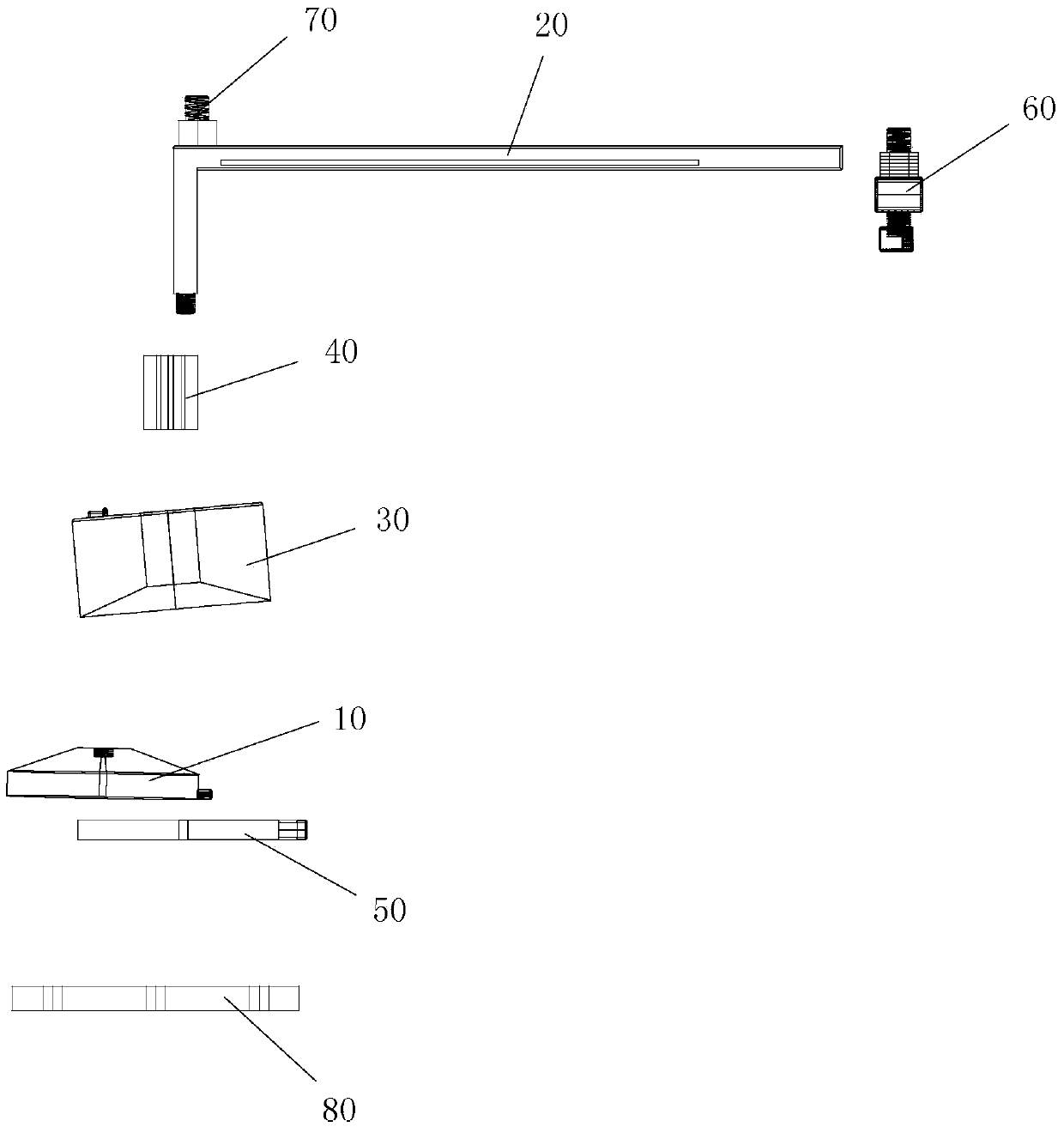
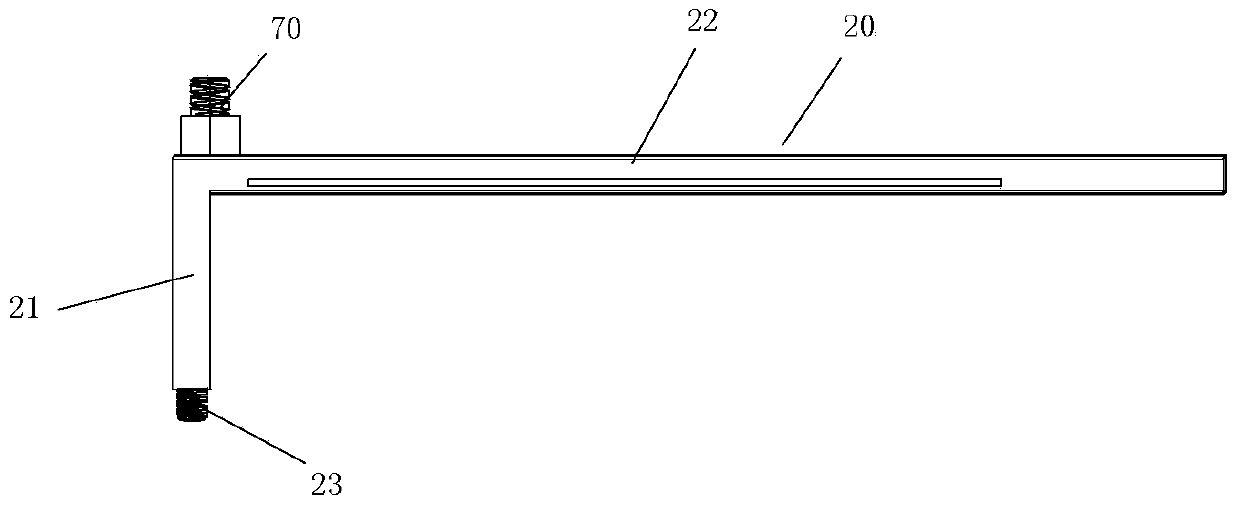
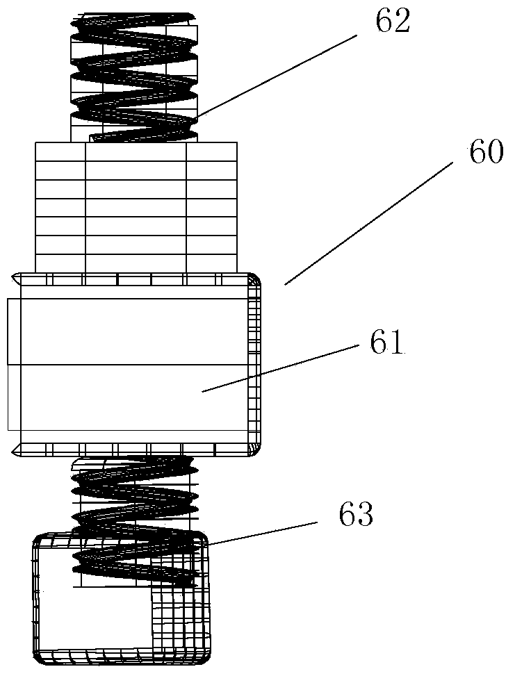
[0039] The present invention provides a positioning detector, please refer to Figure 1 to Figure 8 , the positioning detector comprises: a cantilever 20; an antenna, the antenna position can be adjusted to be installed on the cantilever 20, for collecting the positioning data of its position; a positioning receiver, connected with the antenna signal, for receiving the positioning data collected by the antenna data, and determine the positioning accuracy of the positioning receiver according to the received positioning data collected when the antenna is located at two different cantilever positions of the cantilever 20 and the actual distance between the two cantilever positions.

[0040] The positioning detector in the present invention includes a ...


PUM


Abstract

The invention provides a positioning detector. The positioning detector comprises a cantilever, an antenna and a positioning receiver; the antenna which is installed on the cantilever in an adjustable mode is used for collecting positioning data of a position at which the antenna is arranged; the positioning receiver which is in signal connection with the antenna is used for receiving the positioning data collected by the antenna and confirming the positioning accuracy of the positioning receiver according to the positioning data collected by the antenna at two different positions of the cantilever and the actual distance between the two cantilever positions. The positioning detector has the advantages of being simple in structure, convenient to operate, beneficial to carry, low in cost, high in detection accuracy and high in reliability, satisfying a field work detection requirement for the positioning accuracy, satisfying high-accuracy satellite positioning dynamic receiver requirements for accuracy detection in different industries, being applied to development, detection and calibration of high-accuracy satellite positioning dynamic receivers and having important application values and markets.

Description

technical field [0001] The invention relates to the field of satellite positioning, and more specifically, to a positioning detector. Background technique [0002] The full name of GNSS is Global Navigation Satellite System (Global Navigation Satellite System), which refers to all satellite navigation systems, including GPS in the United States, Glonass in Russia, Galileo in Europe, and Beidou satellite navigation system in China. Provide users with all-weather navigation, positioning and timing services. According to the positioning method, the system can be divided into two types: code-measured pseudo-range and phase-measured pseudo-range. In phase-measured pseudo-range, carrier phase differential positioning is currently the most accurate satellite navigation positioning method. According to the measurement method, it can be divided into static measurement and dynamic measurement. The general observation period of static measurement needs to be observed at a fixed measu...

Claims


Application Information

Patent Timeline
IPC IPC(8): G01S19/23
CPCG01S19/23
Inventor 丁志刚
Owner 北京华宸万泰科技有限公司
Learn More