Rotary-fastening power connection structure

A connection structure and connection bayonet technology, applied in the direction of flexible/rotatable wire connectors, connections, circuits, etc., can solve the problems of poor firmness, inconvenient disassembly and assembly, and inability to be used in combination with common household electrical equipment, and achieve easy disassembly. , The connection is firm, and the effect of improving the stability of the power supply

Inactive Publication Date: 2014-12-10
李安培
View PDF8 Cites 4 Cited by
  • Summary
  • Abstract
  • Description
  • Claims
  • Application Information

AI Technical Summary

Problems solved by technology

[0006] The purpose of the present invention is to overcome the disadvantages of poor firmness, inconvenient disassembly and assembly, and inability to be used in combination with common household electrical equipment in the existing energized connection structure, and to provide a rotary snap-fit ​​energized connection structure, which adopts the technical solution of the present invention and has a simple structure , The connection is firm, easy to disassemble, and the electrical contact is good, especially suitable for the connection of combined multi-functional household electrical equipment

Method used


Image

  • Rotary-fastening power connection structure
  • Rotary-fastening power connection structure
  • Rotary-fastening power connection structure

Examples


Embodiment

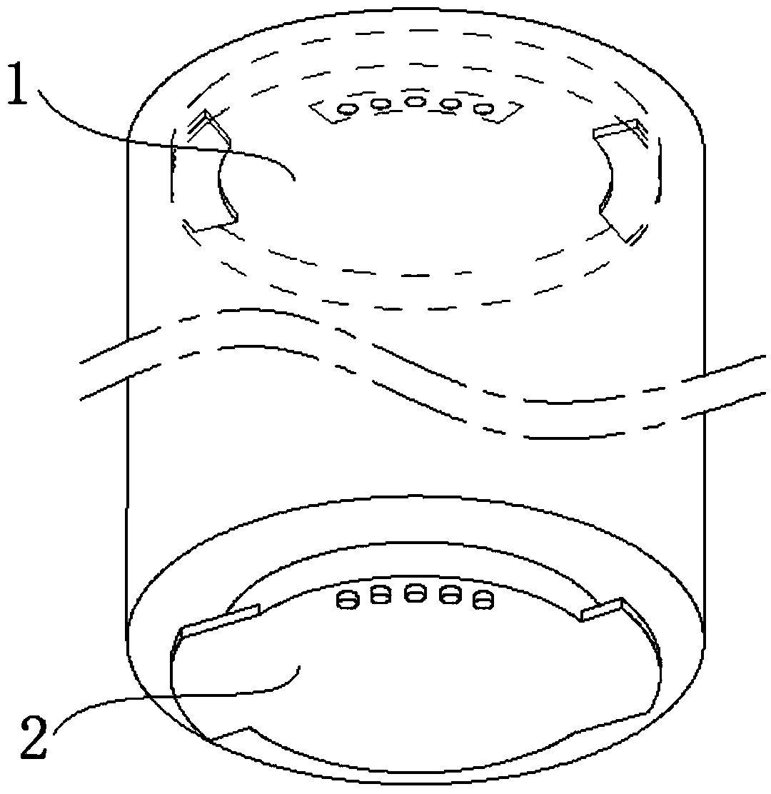
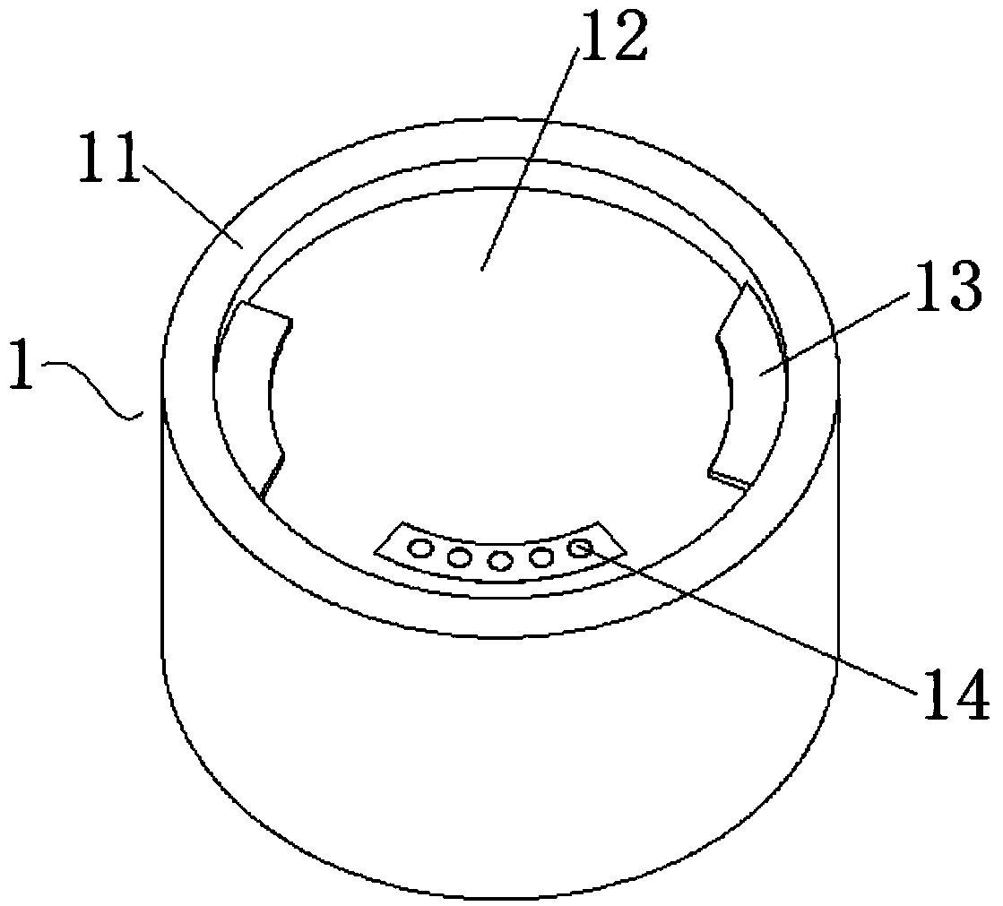
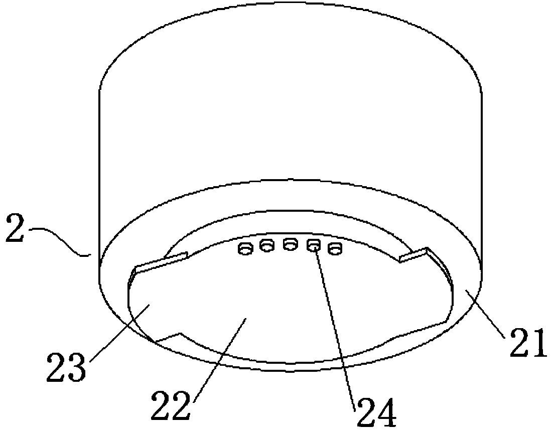
[0031] The rotating snap-in electrical connection structure of this embodiment is a new type of module connection structure, which is mainly aimed at the connection and combination of multiple power consumption modules, while ensuring the power supply of the power consumption modules. combine figure 1 , figure 2 with image 3 , a rotating snap-in electrical connection structure of this embodiment, including a first connection bayonet 1 and a second connection bayonet 2, wherein the first connection bayonet 1 includes a first joint surface 11 and is formed by the first joint surface 11 The inner concave surface 12 formed by inward depression, the first joint surface 11 and the inner concave surface 12 are both planar structures, the first circular side wall is formed between the first joint surface 11 and the inner concave surface 12, and the first circular side wall Two or more first tenons 13 are evenly arranged, and there is a certain gap between the first tenons 13 and t...


PUM


Abstract

The invention discloses a rotary-fastening power connection structure and belongs to the field of connection structures. The rotary-fastening power connection structure comprises a first connecting socket and a second connecting socket. The first connecting socket comprises a first joint surface and a concave surface; a first circular side wall is formed between the first joint surface and the concave surface, a plurality of fastening tongues are arranged on the first circular side wall uniformly, and first power contactors are arranged on the concave surface. The second connecting socket comprises a second joint surface and a convex surface; a second circular side wall is formed between the second joint surface and the convex surface, a plurality of second fastening tongues are uniformly arranged on the second circular side wall, and second power contactors are arranged on the convex surface. The first fastening socket and the second fastening socket are in socket connection; after rotation of the first fastening socket and the second fastening socket, the first fastening tongues and the second fastening tongues are fastened mutually, the first joint surface and the second joint surface fit with each other and the first power contactors contact with the second power contactors. The rotary-fastening power connection structure is simple, firm in connection, convenient to detach and good in power-on contact, and is particularly applicable to connection of combined multifunctional household electric appliances.

Description

technical field [0001] The present invention relates to a connection structure, more specifically, to a rotation-locking electrical connection structure. Background technique [0002] At present, in modern family life, with the continuous improvement of people's requirements for the quality of life, there are more and more indoor daily necessities, especially various household electrical equipment. When all kinds of electrical equipment appear indoors at the same time, it is necessary to lead out a lot of power lines to provide power. These power lines are often messy, occupy a lot of indoor space, cause stumbling, bring a lot of trouble to indoor walking, and easily cause accidents such as electric leakage and electric shock. , especially extremely inconvenient for families with children. Based on the above-mentioned problems, people can't help thinking about whether it is possible to integrate common indoor electrical equipment to reduce the use of power cords. [0003] ...

Claims


Application Information

Patent Timeline
Patent Type & Authority Applications(China)
IPC IPC(8): H01R35/00
Inventor 李安培
Owner 李安培
Why Eureka
Try Eureka