Marine vessel

A ship and hull technology, applied in ship propulsion, ship parts, ship construction, etc., can solve the problems of increased wind pressure resistance, decrease of ship speed, disturbance of air flow, etc., and achieve the effect of reducing wind pressure resistance

Active Publication Date: 2014-12-10
IMABARI SHIPBUILDING
View PDF7 Cites 6 Cited by
  • Summary
  • Abstract
  • Description
  • Claims
  • Application Information

AI Technical Summary

Problems solved by technology

[0008] However, for the above-mentioned ships, for example, the housing of the living quarters and the machinery room are separated, or the height and width of each superstructure are quite different due to the separate design of ea

Method used


Image

  • Marine vessel
  • Marine vessel
  • Marine vessel

Examples


Embodiment Construction

[0024] Hereinafter, embodiments of the ship of the present invention will be described with reference to the drawings.

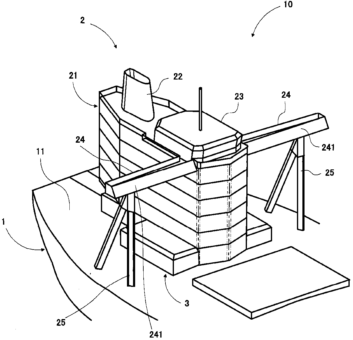
[0025] Such as figure 1 As shown, the ship 10 of the present embodiment includes a hull 1 and a first upper structure 2 provided on an upper deck 11 of the hull 1 via a second upper structure 3 . In addition, in this embodiment, for convenience of description, the bow side of the hull 1 is called "front", and the stern side is called "rear".

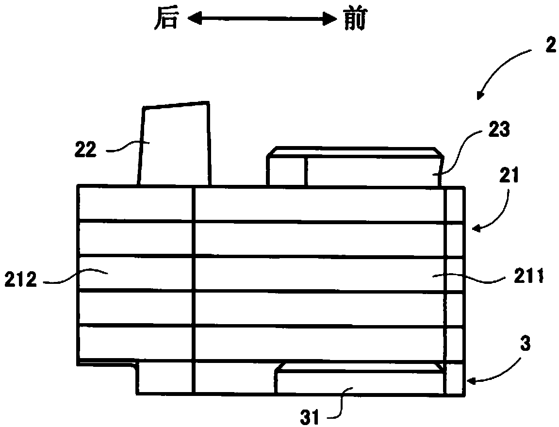
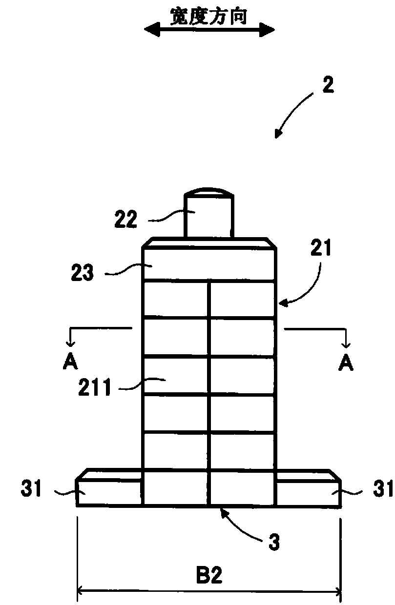
[0026] Such as figure 1 and figure 2 As shown, the first upper structure 2 includes a main body portion 21 including a living area 211 , and a machine room housing 212 adjacent to the rear of the living area 211 and integrally formed with the living area 211 . Additionally, if Figure 1 ~ Figure 3 As shown, the first superstructure 2 includes a chimney 22 and a bridge 23 provided on the main body 21 , and a bridge wing 24 provided on the side surface of the main body 21 .

[0027] In addition, from the viewpoint ...


PUM


Abstract

Provided is a marine vessel having low wind pressure resistance in an upper structural body. A marine vessel comprises: a hull; and a first upper structural body set up on an upper deck of the hull, and having living quarters and an engine room casing adjacent to the living quarters toward the stern of the hull. The first upper structural body has a horizontal cross section formed into a streamlined shape, the living quarters and the engine room casing being formed to the same height.

Description

technical field [0001] The present invention relates to ships. Background technique [0002] For conventional large bulk carriers, oil tankers, etc., the steering room, the living quarters with crew quarters, etc., and the machinery room housing that accommodates the exhaust pipes from the internal combustion engine, etc., are mainly used to vent the exhaust of the internal combustion engine into the air. An upper structure such as a discharge chimney is installed on the upper deck (for example, refer to Patent Document 1). Such superstructures are respectively designed in the smallest shape suitable for various purposes. [0003] 【Prior technical literature】 [0004] 【Patent Literature】 [0005] [Patent Document 1] Japanese Publication No. 62-82295 [0006] 【Invention Outline】 [0007] 【Problems to be solved by the invention】 [0008] However, in the above-mentioned ships, for example, the housing of the living quarters and the machinery room are separated, or the hei...

Claims


Application Information

Patent Timeline
IPC IPC(8): B63B15/00B63H21/32
CPCB63B15/00
Inventor 桧垣和幸
Owner IMABARI SHIPBUILDING
Why Eureka
Try Eureka