
Lens unit

A lens unit and lens technology, applied in optical components, instruments, manufacturing tools, etc., can solve the problems of lower yield, defective, difficult to control position, thickness, etc., and achieve high suppression effect

Inactive Publication Date: 2014-12-10
KONICA MINOLTA INC
View PDF10 Cites 7 Cited by
  • Summary
  • Abstract
  • Description
  • Claims
  • Application Information

AI Technical Summary

Problems solved by technology

However, since the adhesive is difficult to control the position and thickness due to its fluidity, it has the disadvantage of invading into the effective diameter and becoming defective, which tends to lower the yield.

Method used


Image

  • Lens unit
  • Lens unit
  • Lens unit

Examples


Embodiment Construction

[0050] Hereinafter, embodiments of the present invention will be described with reference to the drawings. Figure 5 ~ Figure 8 It is a figure which shows the process of molding the lens array used in this embodiment using a molding die. On the lower surface 11 of the upper mold 10, four optical surface transfer surfaces 12 are protrudingly formed in two rows and two columns. The periphery of each optical surface transfer surface 12 forms a circular step portion 13 protruding from the lower surface 11 by one stage. The upper metal mold 10 can use hard and brittle materials that can also withstand glass forming, for example, materials such as cemented carbide and silicon carbide can be used. In addition, the same applies to the lower mold 20 described below.

[0051] On the other hand, on the upper surface 21 of the lower die 20, a substantially square flat blade land portion 22 is formed, and on the flat upper surface 23 of the flat blade land portion 22, depressions are for...


PUM


Abstract

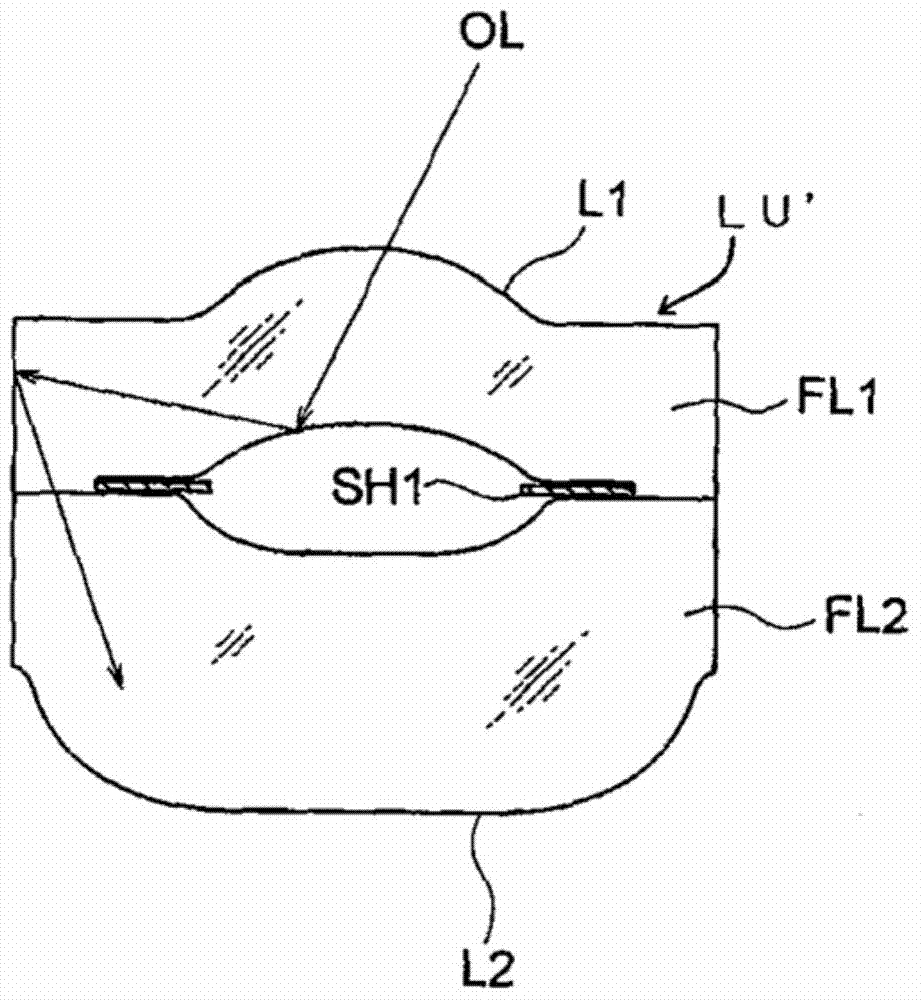
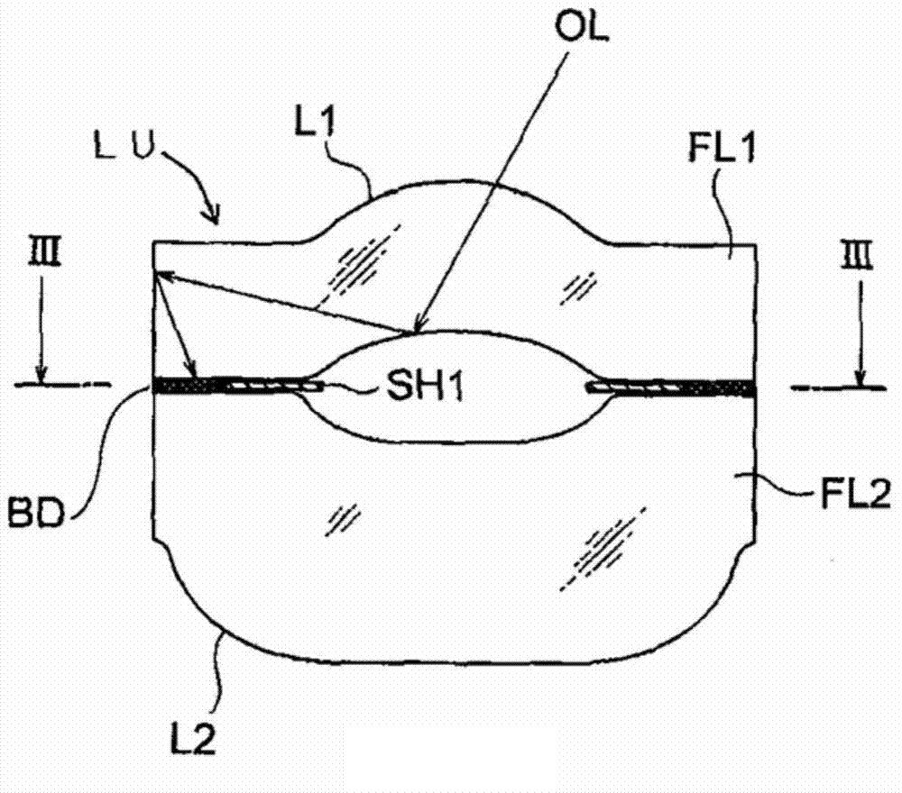
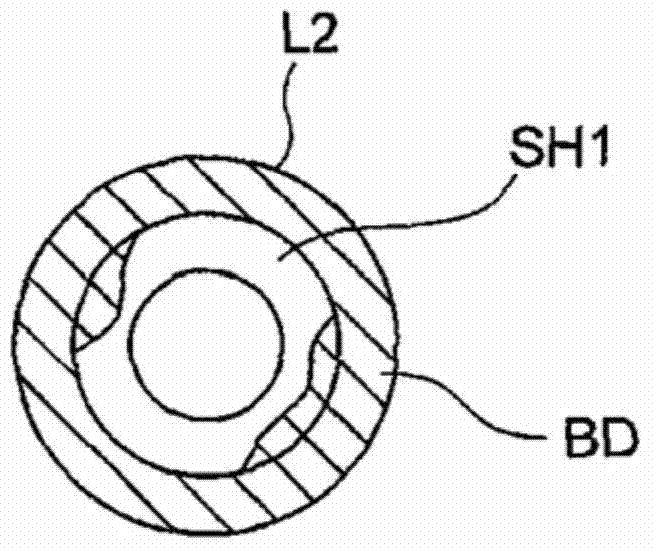
The purpose of the present invention is to provide a lens unit which can create an effective light shield despite the simple process by which the lens unit is produced. A non-transmissive filler (BD) is filled and solidified in the gap between the outer periphery of a light shielding member (SH1) and the outer peripheries of a first lens (L1) and a second lens (L2).

Description

technical field [0001] The present invention relates to a lens unit suitable for an imaging lens and the like. Background technique [0002] Compact and very thin imaging devices (hereinafter also referred to as camera modules) are used in portable terminals such as mobile phones and PDAs (Personal Digital Assistants), which are compact and thin electronic devices. Solid-state imaging elements such as CCD image sensors and CMOS image sensors are known as imaging elements used in these imaging devices. In recent years, the increase in the number of pixels of imaging elements has been increasing, and higher resolution and higher performance have been realized. In addition, in response to miniaturization of imaging elements, there is a demand for downsizing imaging lenses for forming subject images on these imaging elements, and this demand is increasing year by year. [0003] An optical system made of a resin lens is known as an imaging lens used in such an imaging device in...

Claims


Application Information

Patent Timeline
Patent Type & Authority Applications(China)
IPC IPC(8): G02B7/02
CPCG02B5/005C03B2215/414G02B7/022G02B13/0085C03B11/082G02B5/003G02B13/0015G02B13/143
Inventor 水金贵裕新井启司早川周平
Owner KONICA MINOLTA INC
Learn More