Sensor for heart rate detection and wearing structure

A sensor and heart rate technology, applied in the direction of sensors, measuring pulse rate/heart rate, applications, etc., can solve the problems of reducing sensor efficiency, easy cracks, wristband breakage, etc., to avoid dropping or even losing, avoiding accuracy, and improving efficiency effect

Pending Publication Date: 2022-07-29
李健
View PDF1 Cites 0 Cited by
  • Summary
  • Abstract
  • Description
  • Claims
  • Application Information

AI Technical Summary

Problems solved by technology

[0005] In order to solve the above-mentioned technical problems, the present invention provides a sensor and a wearable structure for heart rate detection, to solve the problem that when the sensor on the existing wearable heart rate detection device is installed inside the housing, it is usually connected by a large number of screws. The efficiency of the sensor during installation is greatly reduced, and the belt-type wearable structure on the existing wearable heart rate detection device is generally made of TPU material, which makes the surface of the TPU material prone to cracks after long-term use. After cracks are formed on the surface, it is difficult for people to find them in time, which will further cause the wristband to break, and eventually cause the heart rate detection device to fall or even be lost. It is easy to cause light leakage during detection, which affects the accuracy of detection by the heart rate detection device

Method used


Image

  • Sensor for heart rate detection and wearing structure
  • Sensor for heart rate detection and wearing structure
  • Sensor for heart rate detection and wearing structure

Examples


Embodiment Construction

[0032] The embodiments of the present invention will be described in further detail below with reference to the accompanying drawings and examples. The following examples are intended to illustrate the present invention, but not to limit the scope of the present invention.

[0033] as attached figure 1 to the attached Figure 9 shown:

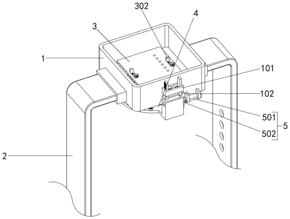
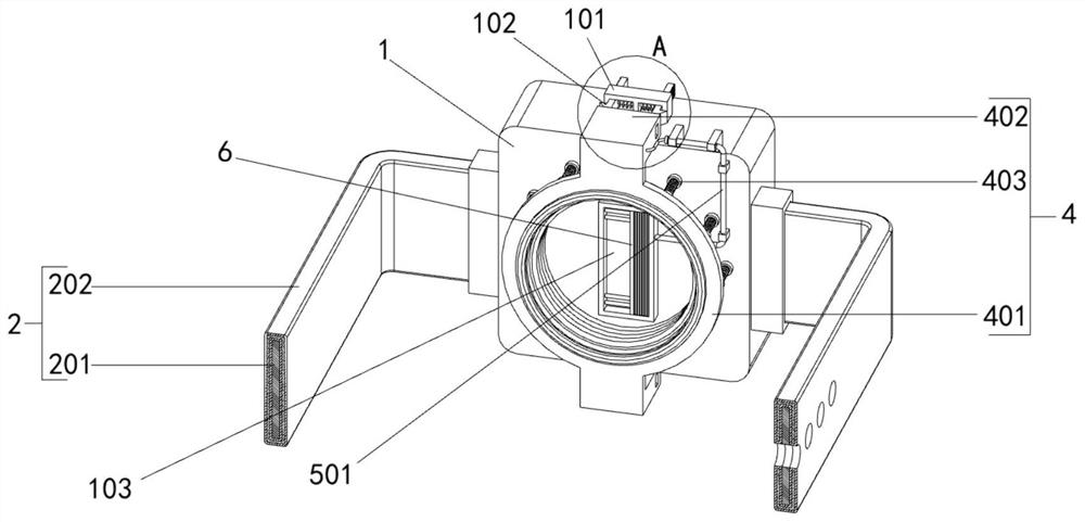
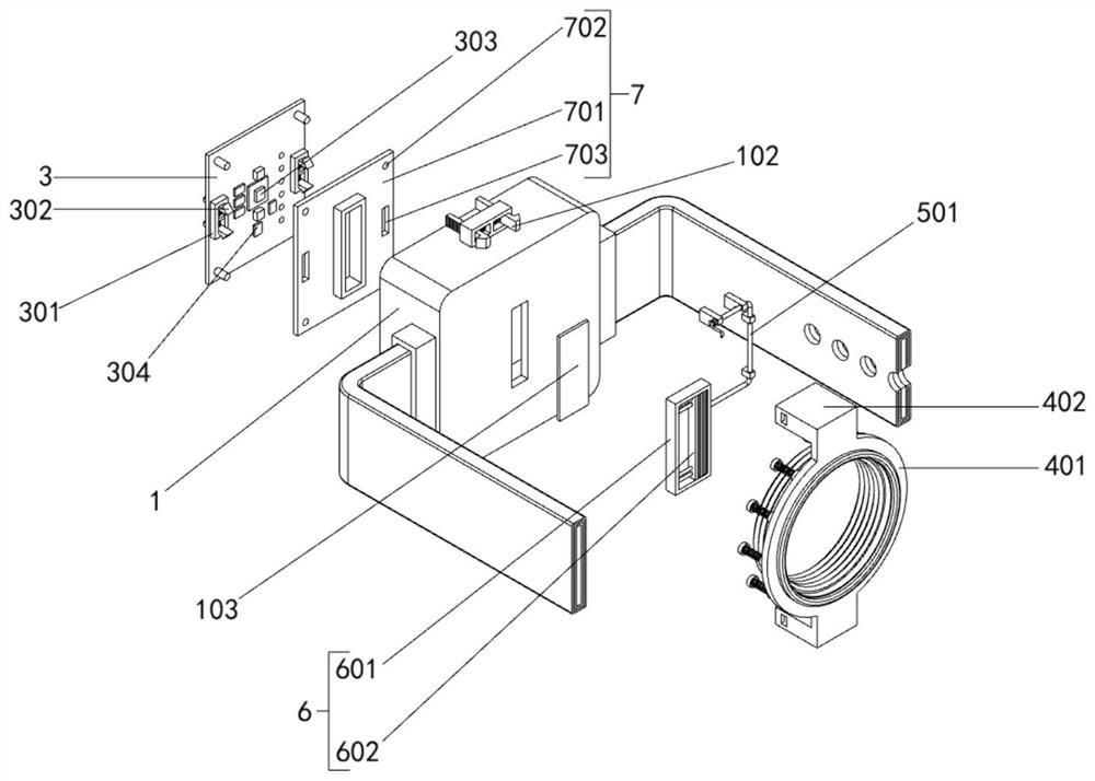
[0034] The present invention provides a sensor for heart rate detection and a wearing structure, comprising: a casing 1; the casing 1 is a square shell-like structure, and a bar-shaped through hole is opened in the middle of the bottom end face of the casing 1; the casing 1 includes a card The mouth branch pipe 101, the first elastic buckle 102 and the transparent glass sheet 103, a bayonet branch pipe 101 is arranged in the middle of the front end face of the casing 1, and the transparent glass sheet 103 is fixed at the strip-shaped opening on the bottom end face of the casing 1. There is a scraping mechanism 6 on the outside of the sheet 1...


PUM


Abstract

The invention provides a sensor for heart rate detection and a wearable structure, belongs to the technical field of heart rate detection, and aims to solve the problem that when a sensor on an existing wearable heart rate detection device is mounted in a shell, the sensor is generally connected through a large number of screws, and then the mounting efficiency of the sensor is greatly reduced. The shell is of a square shell structure, a strip-shaped through opening is formed in the middle of the bottom end face of the shell, and a binding piece is arranged outside the shell. Through the arrangement of the clamping mechanism, when the sensor mainboard is installed, the sensor mainboard is pressed downwards, so that four limiting columns on the sensor mainboard are inserted into four limiting insertion holes in a connecting plate respectively, and meanwhile, four second elastic buckles are clamped with two strip-shaped bayonets respectively, so that the sensor mainboard is fixedly installed in the shell; and in the whole mounting process, a large number of screws are not needed for connection, so that the mounting efficiency of the sensor mainboard is greatly improved.

Description

technical field [0001] The invention belongs to the technical field of heart rate detection, and more particularly, particularly relates to a sensor and a wearing structure for heart rate detection. Background technique [0002] Heart rate usually refers to the number of times the heart beats in one minute, and it reflects the regularity of the heart's activity during a particular cycle. In the past, heart rate measurement was basically only used in medical diagnosis and treatment, and the measurement method of electrocardiogram was used. Today, with the advent and development of the smart wearable craze, heart rate measurement has also begun to be used on wristbands and watches, and has gradually become a standard feature. [0003] For example, application number: CN201410808922.5 The present invention discloses a heart rate detection device, which includes a body, the body includes a face shell and a bottom shell that are fastened to each other, the surface of the face sh...

Claims


Application Information

Patent Timeline
IPC IPC(8): A61B5/024A61B5/00A61B90/00
CPCA61B5/02438A61B5/02416A61B5/681A61B90/08A61B2562/185A61B2090/0809
Inventor 李健
Owner 李健
Why Eureka
Try Eureka