
A kind of processing method of turbocharger floating sleeve

A technology of a turbocharger and a processing method, which is applied in the field of turbocharger machinery, can solve the problems of low production efficiency of a turbocharger floating sleeve, poor accuracy of the inner hole of the turbocharger floating sleeve and an oil wedge surface, and the like, To achieve the effect of saving installation and disassembly tooling time, shortening the turnover process, and improving production efficiency

Active Publication Date: 2016-10-05
CHONGQING JIANGJIN SHIPBUILDING IND
View PDF7 Cites 0 Cited by
  • Summary
  • Abstract
  • Description
  • Claims
  • Application Information

AI Technical Summary

Problems solved by technology

[0003] In order to solve the technical problems of low production efficiency of the floating sleeve of the turbocharger and poor accuracy of the inner hole and the oil wedge surface of the floating sleeve of the turbocharger in the prior art, the present invention provides a processing method for the floating sleeve of the turbocharger. Using the CNC turning and milling center, the milling oil groove can be completed without using the milling oil groove tooling in the same process; without using the turning tool, the mandrel and the inner and outer pressure plates, it can complete the outer circle of the finish turning and the inner hole of the semi-finish turning, and drill the oil hole And anti-rotation pin hole, cutting end face, inner hole and outer circle chamfering, which saves the installation and disassembly tooling time and also shortens the turnover process, improves production efficiency, ensures the coaxiality requirements of the inner hole and outer circle, and is one-time Milling the inner hole and the oil wedge surface to ensure the coaxiality and surface roughness of the inner hole and the oil wedge surface

Method used


Image

  • A kind of processing method of turbocharger floating sleeve
  • A kind of processing method of turbocharger floating sleeve
  • A kind of processing method of turbocharger floating sleeve

Examples


Embodiment Construction

[0022] The specific implementation manner of the present invention will be described in further detail below in conjunction with the accompanying drawings.

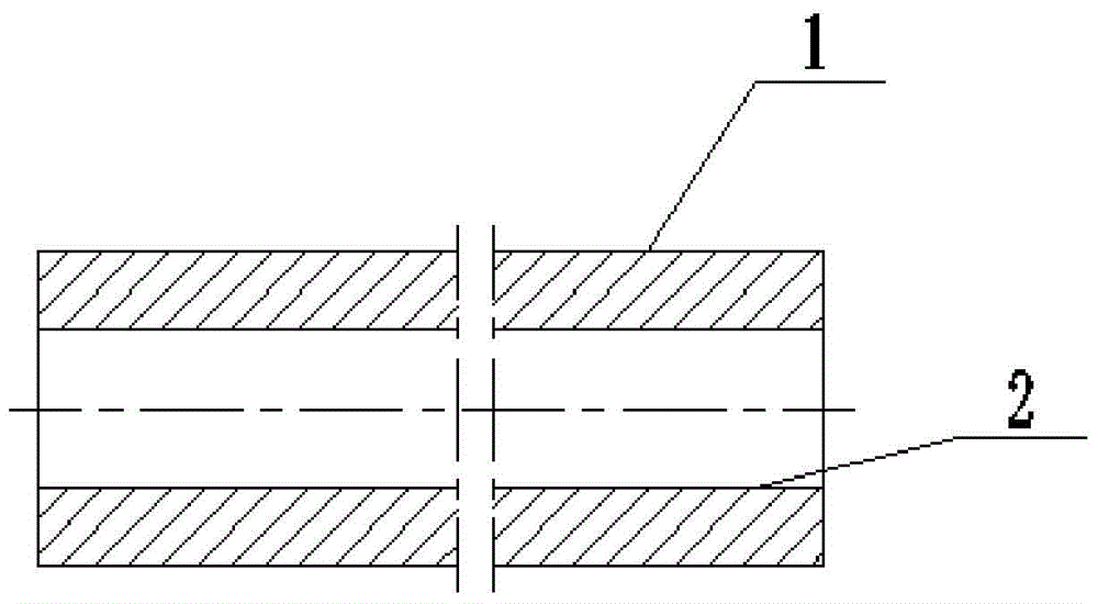
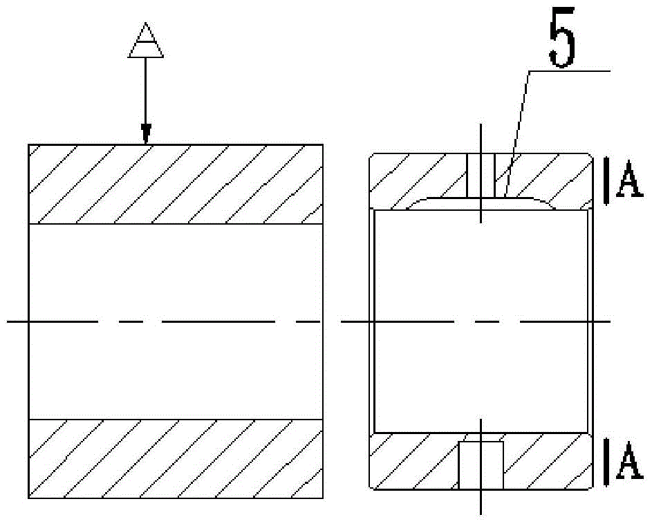
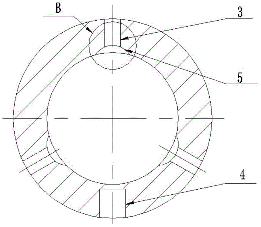
[0023] Such as figure 1 , figure 2 , image 3 and Figure 4 Shown, the present invention is a kind of turbocharger floating sleeve processing method, comprises the following steps:

[0024] (1) Rough turning outer circle 1 and inner hole 2;

[0025] (2) Turn the inner hole 2 and the outer circle 1 of the CNC turning and milling center, then drill three oil inlet holes 3 and one anti-rotation pin hole 4, mill the oil groove 5 corresponding to the three oil inlet holes, and finish turning the outer circle 1 and half Finish turning the inner hole 2, chamfer the outer circle and inner hole of the non-cut end, cut according to the length, mark the non-cut end face A; then turn around, and chamfer the outer circle and inner hole of the cut end;

[0026] (3) Remove all orifice burrs, and grind and cut off the end face;

...


PUM


Abstract

The invention discloses a machining method for a floating bush of a turbocharger. The machining method comprises the following steps: roughly turning the outer circle and an inner hole; turning the inner hole and the outer circle by a numeric control turn-milling center; drilling three oil inlet holes and an anti-rotating pin hole; milling oil tanks corresponding to the three oil inlet holes; performing finish turning on the outer circle and performing semi-finish turning on the inner hole; chamfering the outer circle and the inner hole of a non-cut end; cutting lengthwise; marking the non-cut end face; turning round; chamfering the outer circle and the inner hole of the cut end; removing all burrs at the orifices; grinding the cut end face; milling the inner hole and the oil tanks; removing all burrs; performing comprehensive inspection. The machining method for the floating bush of the turbocharger guarantees the accuracy of the inner hole, the oil tanks and oil wedge surfaces and improves the production efficiency, so that the machining time is shortened from original 3.93m / piece to 2.35m / piece.

Description

technical field [0001] The invention relates to the mechanical field of a turbocharger, in particular to a processing method for a floating sleeve of a turbocharger. Background technique [0002] The turbocharger on the diesel engine is a high-speed running part, and the floating sleeve on the turbocharger is used as a floating bearing to support the high-speed operation of the turbine shaft. Therefore, the quality of the floating sleeve, which is a key part of the core component of the turbocharger, directly Affects the use of turbochargers. The processing steps of the existing floating sleeve are as follows: (1) rough turning the outer circle and inner hole; (2) turning the end face, outer circle and inner hole, cutting off, and marking the non-cut end face; (3) milling three oil inlet holes and a Anti-rotation pin hole; (4) milling oil groove tool, milling the three oil grooves corresponding to the three oil inlet holes in the inner hole; (5) deburring, grinding and cutt...

Claims


Application Information

Patent Timeline
Patent Type & Authority Patents(China)
IPC IPC(8): B23P15/00
CPCB23P15/00
Inventor 段昌文胡亚姚胜蒋利
Owner CHONGQING JIANGJIN SHIPBUILDING IND
Learn More