

Silicon rod clamp for sawing machine
A sawing machine, silicon rod technology, applied in the direction of manufacturing tools, work accessories, stone processing equipment, etc., can solve problems such as poor product quality, and achieve the effects of less damage, improved work efficiency, and convenient fixation and disassembly.
- Summary
- Abstract
- Description
- Claims
- Application Information
AI Technical Summary
Problems solved by technology
Method used
Image

Examples
Embodiment 1
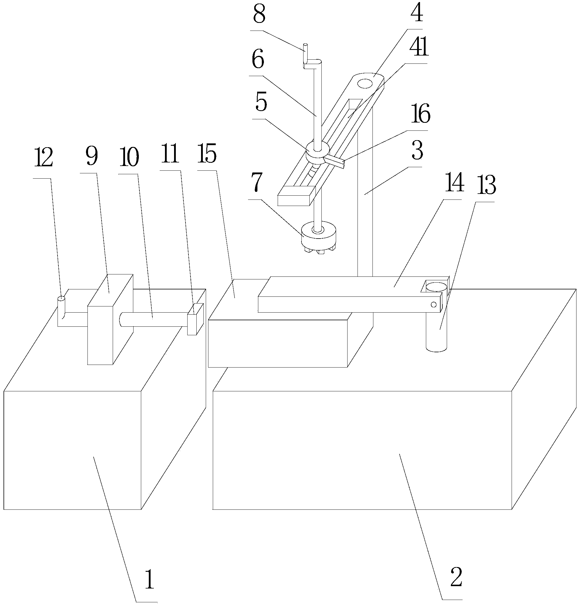
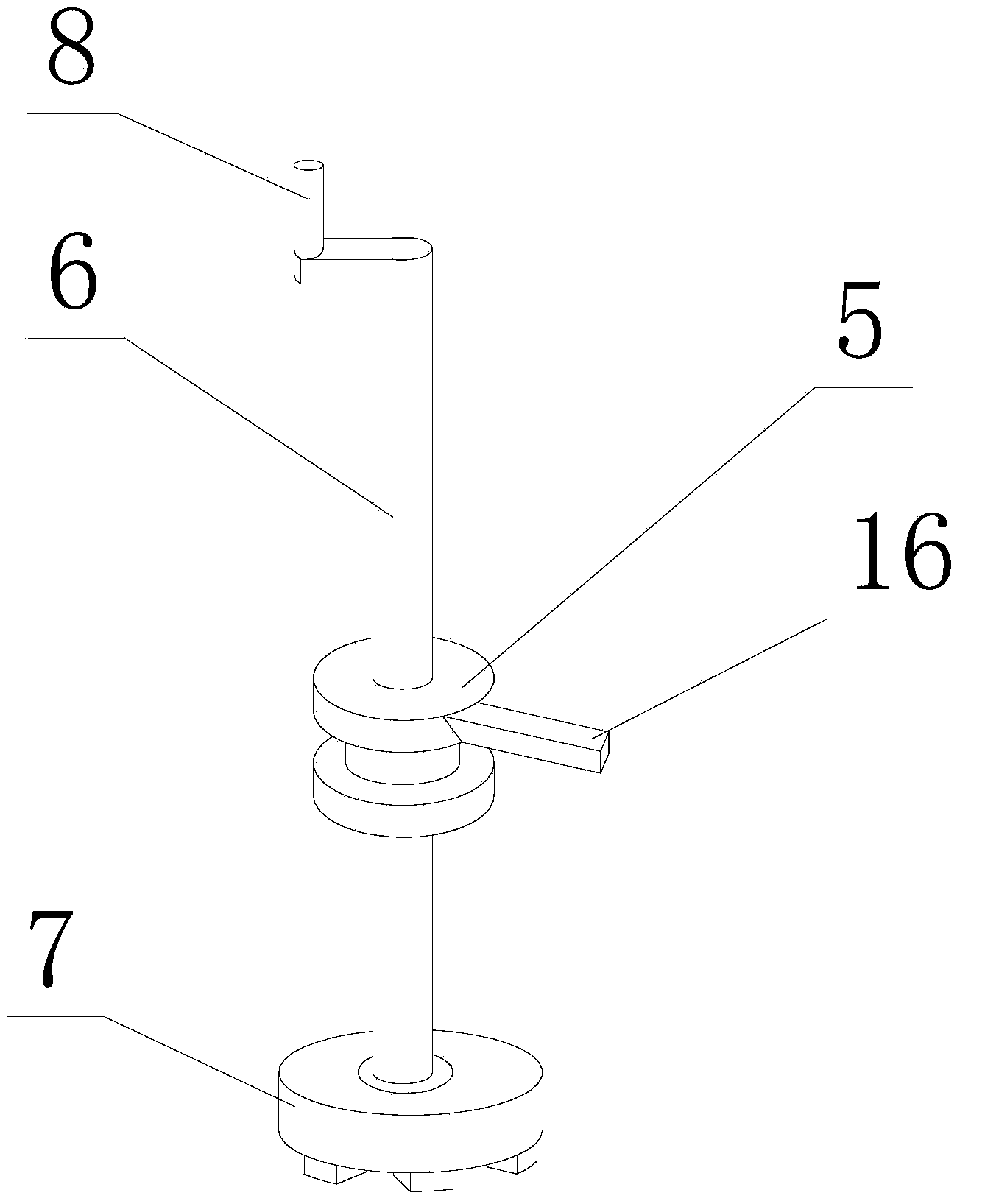
[0018] refer to figure 1 and figure 2 , the cross-section of the silicon rod 15 is rectangular; a silicon rod clamp for a sawing machine, including a left support platform 1 arranged on the left side of the saw blade, a right support platform 2 arranged on the right side of the saw blade, for fixing the silicon rod 15 The pressing device on the right support platform 2, the positioning device that is arranged on the left support platform 1 and can move left and right relative to the left support platform 1; The column 3, the horizontal bar 4 fixedly connected to the upper end of the column 3 and provided with a bar-shaped hole 41, the slider 5 that is clamped on the horizontal bar 4 and can move along the bar-shaped hole 41, is threaded through the slider 5 and The vertically arranged first screw rod 6, the briquetting block 7 arranged at the lower end of the first screw rod 6, and the handle 8 fixedly connected to the upper end of the first screw rod 6; , the second screw ...
Embodiment 2
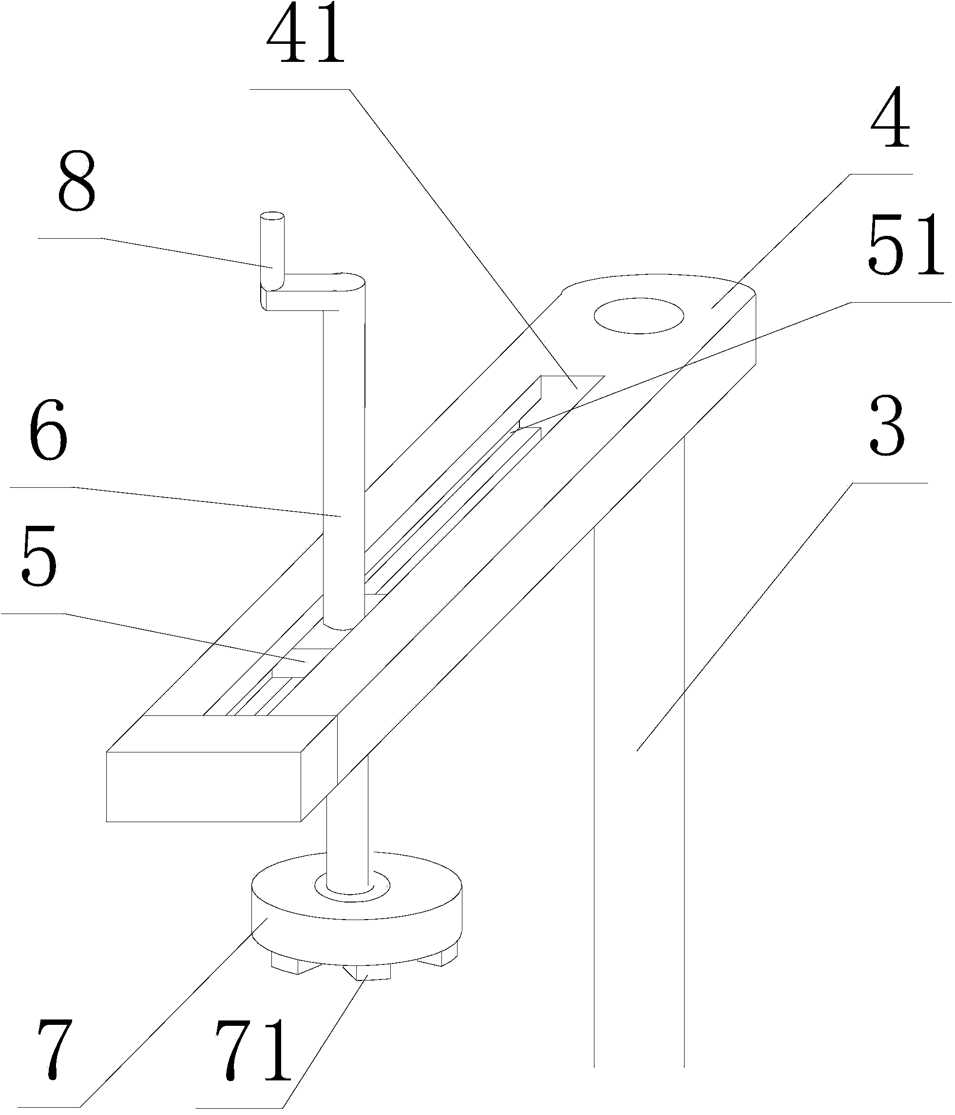
[0021] refer to image 3 , the difference with Embodiment 1 is that: the slider 5 is a cuboid, the center of the slider 5 has a threaded hole, and both sides of the inner wall of the strip hole 41 are provided with a 5 grooves 51 .
[0022] The fixing and dismounting of the silicon rods in the invention is relatively convenient, which improves the work efficiency, causes little damage to the silicon rods when clamping the silicon rods, reduces the scrap rate of products, and the positioning device can improve the processing accuracy of products.
PUM
 Abstract
Description
Claims
Application Information