retractable submarine
A telescopic and submarine technology, which is applied in the direction of underwater ships, ships, underwater operation equipment, etc., can solve the problems of complex manufacturing process, few functions of submarines, and easy discovery of large targets, so as to shorten the production period and resist pressure. Strong, low resistance effect
- Summary
- Abstract
- Description
- Claims
- Application Information
AI Technical Summary
Problems solved by technology
Method used
Image
Examples
Embodiment 1
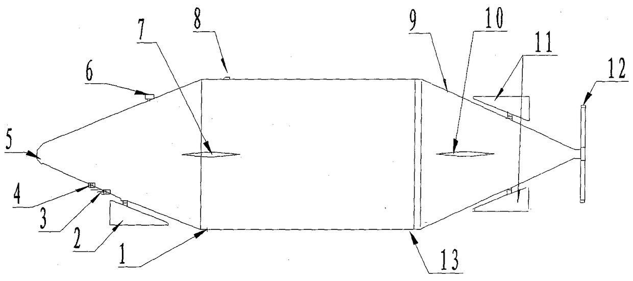
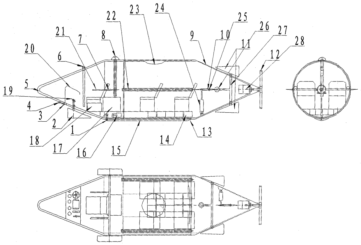
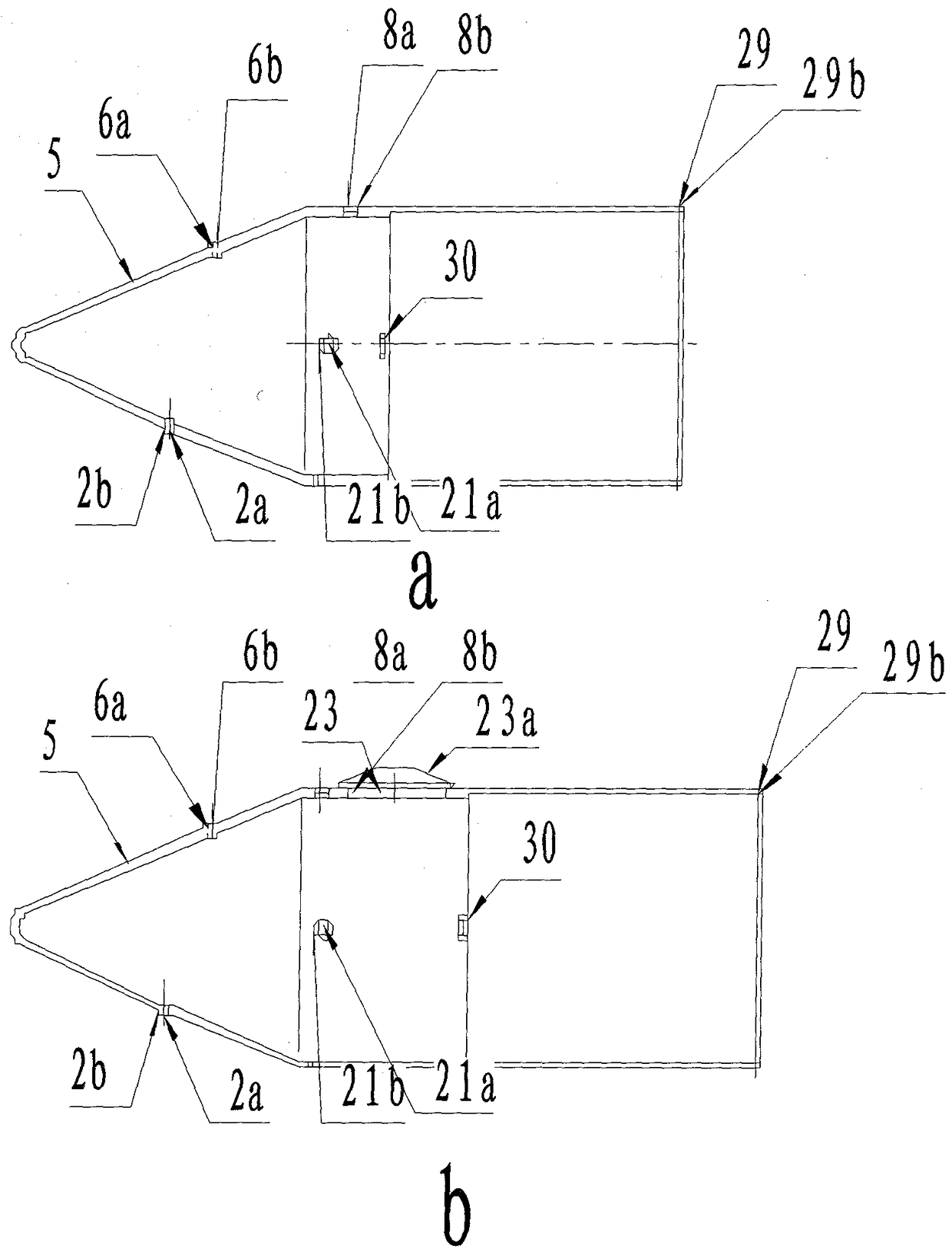
[0021] see figure 1 , figure 2 Shown: embodiment 1 is a kind of retractable submarine, and it comprises an outer hull (5) and an inner hull (9). Described outer hull (5) is the shell of retractable submarine, and the front end is tapered tubular shape, and the back is round tubular shape, and the shell is provided with seal groove (29), hull sealing ring (29b), front steering rudder hole ( 2a), sealing ring (2b), periscope hole (6a), sealing ring (6b), telescopic ventilation pipe hole (8a), sealing ring (8b), etc.;
[0022] see image 3 , as shown: image 3 a is the hatch type outer hull, image 3 b is that the hatch type outer hull has one more hatch cover than the hatch type outer hull, and the others are all the same; the two kinds of outer hulls are equipped with hydraulic hooks (1), front steering rudders (2), lighting lamps (3 ), electronic probe (4), periscope (6), elevator (7), telescopic air exchange tube (8), hanging column (13), counterweight (15), hydraulic p...
Embodiment 2
[0027] see Figure 5 Shown: embodiment 2 is a telescopic ventilation pipe (8), and telescopic ventilation pipe (8) is made of telescopic pipe (36), sealing bowl (39), exhaust pipe (46), intake pipe (47) hydraulic cylinder ( 49) and three fork split sheet (48) form. The three-prong split piece (48) is divided into three cavities in the telescopic tube (36), and an intake pipe (47), an exhaust pipe (46) and a hydraulic cylinder (49) are respectively placed in each cavity, and each cavity top An air inlet (42), an air outlet (41) and an air vent (40) are respectively provided. The trident segment (48), the sealing bowl (39), the hydraulic cylinder barrel (44) and the telescopic tube (36) are fixed together. The piston rod (45) is provided with the lower end of the oil passage (50) extending out to be connected with the housing of the internal combustion generator. After the submarine rises and emerges from the water surface, oil filling is extended to the oil passage (50), and...
Embodiment 3
[0029] see Figure 6 Shown: embodiment 3 is a kind of hydraulic hook, is made up of hook (51), bearing pin (52), piston rod (53) and hydraulic cylinder barrel (56) and sealing ring (55b). The hydraulic cylinder (56) is fixed in the outer hull, the piston rod (53) protrudes from the hanging hole of the outer hull, and the hanging hole is provided with a sealing groove (1a) and a sealing ring (1b) to form a seal with the piston rod (53), Fill the upper oil hole (57) with oil, the piston rod (53) will stretch out, and the hook (51) will open when it leaves the hanging hole tube bundle, (see Figure 6 e) The hanging counterweight will fall off. Fill the oil hole (54) down, the piston rod (53) is retracted, and the hook (51) is carried on the hook (51) and is squeezed and closed by the hanging hole of the outer hull, (see Figure 6 f) until the counterweight is tightened.
PUM
 Abstract
Description
Claims
Application Information
 - R&D
- Intellectual Property
- Life Sciences
- Materials
- Tech Scout
- Unparalleled Data Quality
- Higher Quality Content
- 60% Fewer Hallucinations
Browse by: Latest US Patents, China's latest patents, Technical Efficacy Thesaurus, Application Domain, Technology Topic, Popular Technical Reports.
© 2025 PatSnap. All rights reserved.Legal|Privacy policy|Modern Slavery Act Transparency Statement|Sitemap|About US| Contact US: help@patsnap.com


