
Warping system

A tensioning frame, reciprocating technology, used in warping machines, textiles and papermaking, manufacturing tools, etc., can solve the problems of broken threads, wear of rotating parts, wear of warp yarns, etc., to avoid wear and broken threads.

Inactive Publication Date: 2014-12-17
安吉县青云麻纺织厂
View PDF8 Cites 10 Cited by
  • Summary
  • Abstract
  • Description
  • Claims
  • Application Information

AI Technical Summary

Problems solved by technology

For example: a kind of warping machine described in Patent No. CN203174263U includes a frame and a bobbin, on which a number of warps are wound, and it also includes a rotary member for adjusting the tension of the warp thread, a warp beam and a splitting reed, and the splitting reed The reed is movably set on the frame, the sub-twisted reed has a plurality of reed teeth, the bottom of the frame is set on the sliding track, the two ends of the sliding track are provided with travel switches, and the sliding track is controlled by the controller , which adjusts the curling angle of the warp yarn by moving the frame and the split reed on the frame. The disadvantage is that the warp yarn has been moving on the surface of the rotary part, causing wear on the rotary part, and it is easy to cause warp yarn wear and thread breakage

Method used


Image

  • Warping system
  • Warping system

Examples


Embodiment Construction

[0013] The present invention will be described in further detail below in conjunction with the accompanying drawings.

[0014] This specific embodiment is only an explanation of the present invention, and it is not a limitation of the present invention. Those skilled in the art can make modifications to this embodiment without creative contribution as required after reading this specification, but as long as they are within the rights of the present invention All claims are protected by patent law.

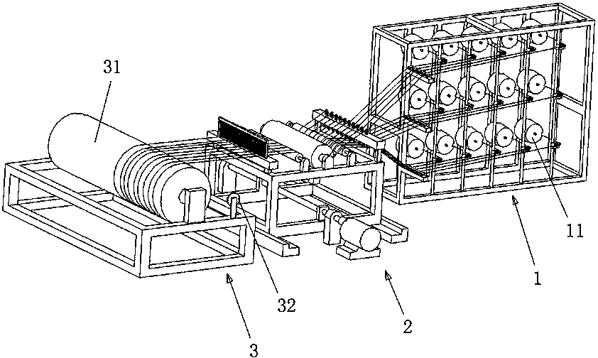
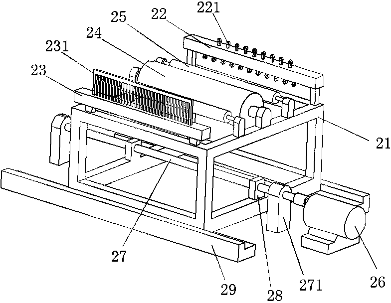
[0015] Examples such as figure 1 and figure 2 Shown: a warping device, including a creel 1, a tensioning mechanism 2 and a take-up mechanism 3, the creel 1 is provided with multiple layers, each layer is inserted with a cheese 11. The tensioning mechanism 2 includes a tensioning frame 21 and a rotating member arranged on the tensioning frame 21 . The winding mechanism 3 includes a yarn reel 31 and a speed measuring and length measuring device 32, and the reel 31 is driven by a...


PUM


Abstract

The invention relates to the field of textile machinery, in particular to a warping system, which comprises a bobbin creel, a tensioning mechanism and a take-up mechanism, the bobbin creel is provided with a plurality of layers, and cheeses are planted on each layer; the tensioning mechanism comprises a tensioning carriage and rotary parts; the take-up mechanism comprises a spool and a speed and length measurement device; the warping system is characterized in that the tensioning carriage is provided with a reciprocating device, which can drive the tensioning mechanism to move to and fro along the axial direction of the spool. By arranging the reciprocating device, the tensioning mechanism can periodically move to and fro, thus ensuring that the spool can uniformly wind yarns and preventing the problem that the yarns are wound excessively on one end and insufficiently on the other end, meanwhile, because yarn guides and a raddle are arranged at the yarn inlet and yarn outlet of the tensioning carriage, the yarns can be prevented from rubbing the surfaces of the rotary parts to abrade and break when the tensioning mechanism moves to and fro.

Description

technical field [0001] The invention relates to the field of textile machinery, in particular to a warping device. Background technique [0002] The function of the warping machine is to wind the warp yarn wound on the bobbin in parallel on the warp shaft according to the number, length and width required by the process design, for use in the sizing or drawing-in process. In order to allow the warp yarns to be evenly wound on the entire warp beam, it is necessary to constantly adjust the curling angle of the warp yarns during the winding process. For example: a kind of warping machine described in Patent No. CN203174263U includes a frame and a bobbin, on which a number of warps are wound, and it also includes a rotary member for adjusting the tension of the warp thread, a warp beam and a splitting reed, and the splitting reed The reed is movably set on the frame, the sub-twisted reed has a plurality of reed teeth, the bottom of the frame is set on the sliding track, the two...

Claims


Application Information

Patent Timeline
Patent Type & Authority Applications(China)
IPC IPC(8): D02H3/00
Inventor 尤一群
Owner 安吉县青云麻纺织厂
Learn More