A four-degree-of-freedom outer rotor magnetic bearing

An external rotor and magnetic bearing technology, applied in the field of four-degree-of-freedom external rotor magnetic bearings, can solve the problems of complex circuit, poor stability, high power consumption, etc., and achieve the effects of high control accuracy, small magnetic field fluctuation, and low rotational power consumption.

Active Publication Date: 2017-02-15
BEIHANG UNIV
View PDF4 Cites 0 Cited by
  • Summary
  • Abstract
  • Description
  • Claims
  • Application Information

AI Technical Summary

Problems solved by technology

In order to increase the output torque, the existing magnetic levitation control torque gyroscope usually adopts a five-degree-of-freedom fully active magnetic bearing configuration. However, the magnetic levitation control torque gyroscope with this structure uses current to control the output torque, so it consumes a lot of power and is bulky. , the circuit is complex, and the two-degree-of-freedom magnetic levitation control torque gyroscope with passive magnetic bearing output torque can be made very small, but because the passive magnetic bearing is uncontrollable, it has the defects of low damping and poor stability. In addition, the existing four There is an interaction between the stiffness of the active part of the degree of freedom magnetic bearing and the stiffness of the passive part, which will increase the control difficulty of the control system

Method used


Image

  • A four-degree-of-freedom outer rotor magnetic bearing
  • A four-degree-of-freedom outer rotor magnetic bearing
  • A four-degree-of-freedom outer rotor magnetic bearing

Examples


Embodiment Construction

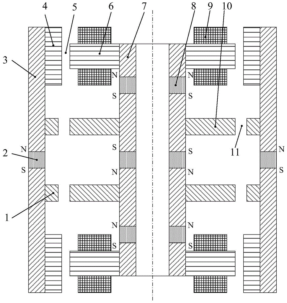
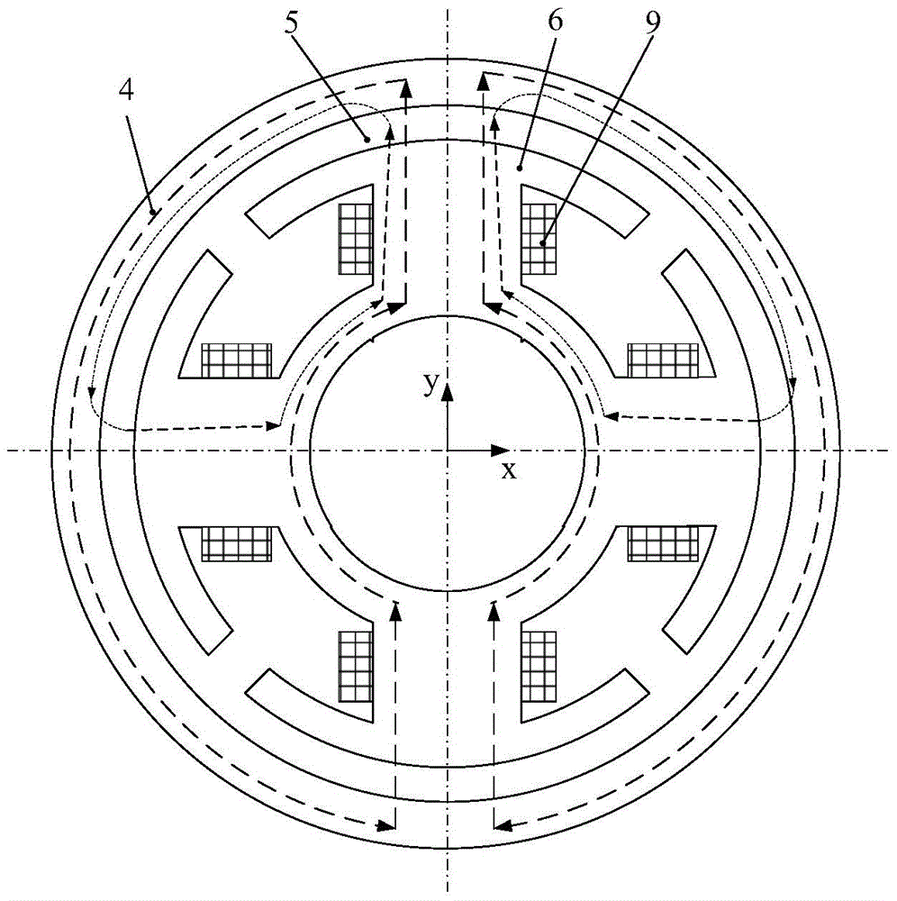
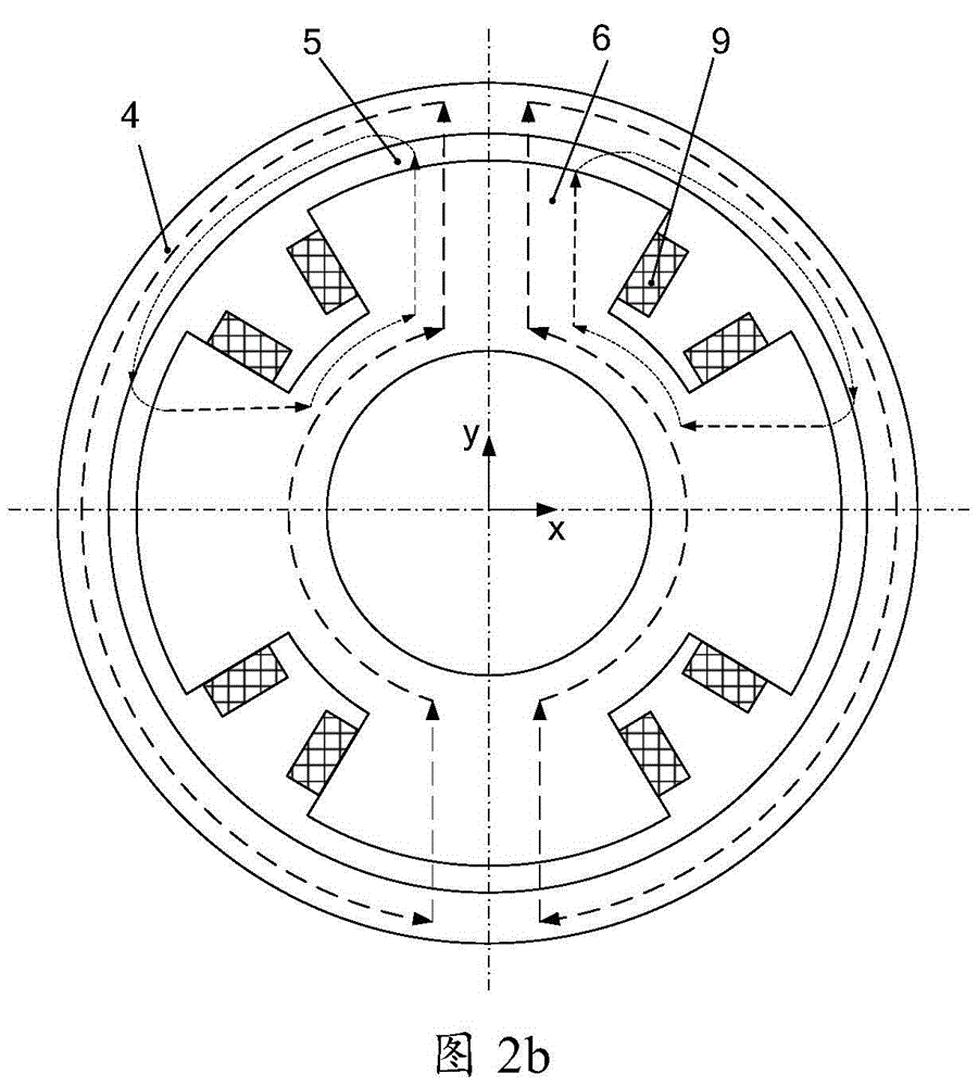
[0017] Such as figure 1 As shown, a four-degree-of-freedom outer rotor magnetic bearing is composed of the outer rotor magnetic ring 1 of the passive part, the outer rotor permanent magnet 2, the outer rotor magnetic body 3, the outer rotor core 4, the air gap 5, the stator core 6, the stator guide The magnetic ring 7, the stator permanent magnet 8, the coil 9, the passive part of the stator magnetic ring 10 and the passive part of the air gap 11, wherein each stator core 6 is composed of 4 magnetic poles, and two stator cores 6 form the upper and lower ends of the magnetic bearing 8 magnetic poles, which form the magnetic poles in the positive and negative directions of the X and Y axes respectively. A coil 9 is wound on the magnetic pole of each stator core 6. The outside of the stator core 6 is the outer rotor core 4, and the outside of the outer rotor core 4 is the outer rotor magnetizer. 3. There is a certain gap between the inner surface of the outer rotor core 4 and th...


PUM


Abstract

The invention discloses a four-degree-of-freedom outer rotor magnetic bearing. The four-degree-of-freedom outer rotor magnetic bearing consists of driven part outer rotor magnetic conducting rings, an outer rotor permanent magnet, outer rotor magnetic conducting bodies, outer rotor iron cores, air gaps, stator iron cores, a stator magnetic conducting ring, stator permanent magnets, a coil, driven part stator magnetic conducting rings and driven part air gaps, wherein each of the stator iron cores consists of four magnetic poles forming magnetic poles in the positive and negative directions of X and Y axles; certain gaps are left between the inner surfaces of the outer rotor iron cores and the outer surfaces of the stator iron cores, and form the air gaps; the two driven part stator magnetic conducting rings are positioned between the two stator iron cores; two stator permanent magnets are arranged between the stator iron cores and the driven part stator magnetic conducting rings; a stator permanent magnet is arranged between the two driven part stator magnetic conducting rings; the outer rotor permanent magnet is arranged between the two outer rotor magnetic conducting bodies; and the driven part air gaps are formed between the inner surfaces of the driven part outer rotor magnetic conducting rings and the outer surfaces of the driven part stator magnetic conducting rings. The four-degree-of-freedom outer rotor magnetic bearing has the characteristics of small size and easy assembly and disassembly.

Description

technical field [0001] The invention relates to a non-contact magnetic suspension bearing, in particular to a four-degree-of-freedom outer rotor magnetic bearing, which can be used as a non-contact support for rotating components such as a single-frame control moment gyroscope and a double-frame control moment gyroscope for space. Background technique [0002] Magnetic suspension bearings are divided into pure electromagnetic type and hybrid magnetic suspension bearing with permanent magnetic bias and electromagnetic control. The former uses large current and high power consumption, and the hybrid magnetic suspension bearing with permanent magnetic bias and electromagnetic control uses permanent magnets instead of pure electromagnetic magnetic bearings. The bias current in the bearing generates a bias magnetic field, the magnetic field generated by the permanent magnet bears the main bearing capacity, and the electromagnetic field provides an auxiliary adjustment bearing capa...

Claims


Application Information

Patent Timeline
Patent Type & Authority Patents(China)
IPC IPC(8): F16C32/04
Inventor 孙津济汤继强刘虎韩伟涛乐韵
Owner BEIHANG UNIV
Why Eureka
Try Eureka