A soaked film heat exchanger

A heat exchanger and thin-film technology, which is applied in the field of immersion thin-film heat exchangers, can solve the problems of high requirements, dry spot production and installation, and high requirements for liquid distribution, so as to achieve good film-forming performance and save costs Effect

Active Publication Date: 2016-04-20
严格集团股份有限公司
View PDF4 Cites 0 Cited by
  • Summary
  • Abstract
  • Description
  • Claims
  • Application Information

AI Technical Summary

Problems solved by technology

[0003] The purpose of the present invention is to provide a soaked film heat exchanger to solve the problem that the current traditional falling film heat exchanger has relatively high requirements for liquid distribution, is easy to form "dry spot phenomenon" and has relatively high requirements for production and installation. asked questions

Method used


Image

  • A soaked film heat exchanger
  • A soaked film heat exchanger
  • A soaked film heat exchanger

Examples


specific Embodiment approach 1

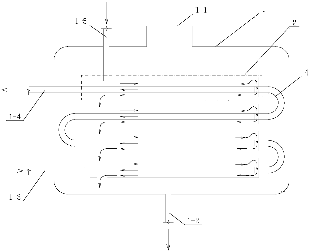
[0014] Specific implementation mode one: combine Figures 1 to 4 Describe this embodiment, this embodiment includes a housing 1, in which a plurality of heat exchange units 2 are arranged sequentially from top to bottom, and two adjacent heat exchange units 2 are arranged in the same direction, and the side wall or top of the housing 1 is provided with A steam port 1-1 and a first heat exchange medium inlet pipeline 1-5, the bottom of the shell 1 is provided with a first heat exchange medium outlet 1-2, and the side wall of the shell 1 is provided with a second heat exchange medium inlet pipeline 1-3 and the second heat exchange medium outlet pipeline 1-4,

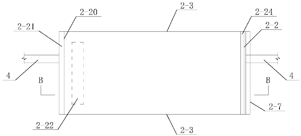
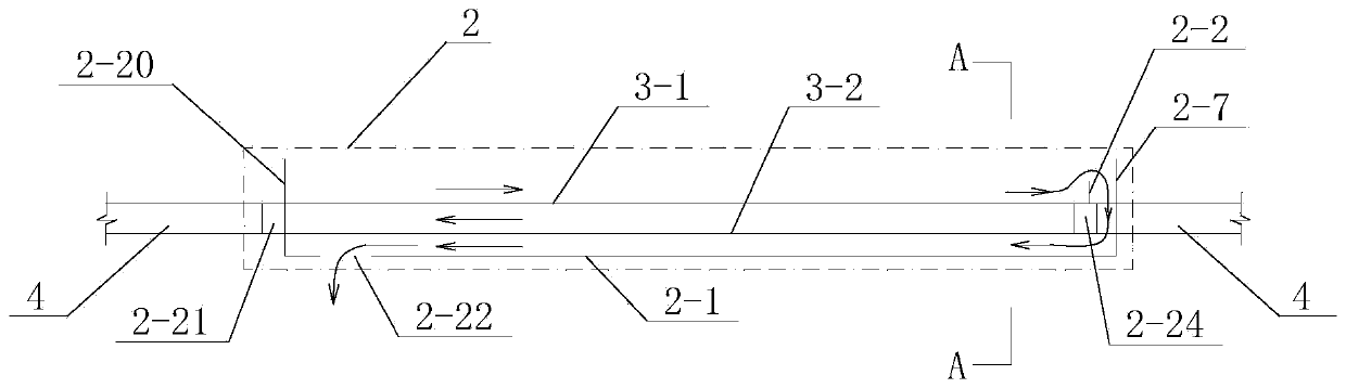
[0015] Each heat exchange unit 2 includes a supporting plate 2-1, an upper heat exchange plate 3-1, a lower heat exchange plate 3-2, a first baffle plate 2-2, a third baffle plate 2-7, and a fourth baffle plate 2 -20, the first header box 2-21, the second header box 2-24 and two second baffles 2-3, the supporting plate 2-...

specific Embodiment approach 2

[0018] Specific implementation mode two: combination figure 1 , 5 , 6 and 7 illustrate the present embodiment, the supporting plate 2-1 of the present embodiment has several spray holes 2-6. Other implementation manners are the same as the specific implementation manner 1.

specific Embodiment approach 3

[0019] Specific implementation mode three: combination figure 1 and 8 This embodiment will be described. The upper heat exchange plate 3-1 and the lower heat exchange plate 3-2 of this embodiment are corrugated plates. Other implementations are the same as the first or second implementation.


PUM


Abstract

The invention provides an immersed film type heat exchanger, and relates to the technical field of the exchanger. The problems that the traditional falling film type heat exchanger has high requirements on cloth liquid, easily generates dry spot phenomenon, and has high requirements on manufacturing and mounting are solved. The first scheme is that multiple heat exchanging units are sequentially arranged in a casing from top to bottom in an aligned way, and two adjacent heat exchanging units are arranged at the same direction; a slab joint type channel defined by an upper heat exchanging plate, a lower heat exchanging plate and two second baffle plate forms a second heat exchanging medium passage in the heat exchanging unit. The second scheme is that multiple heat exchanging units are sequentially arranged in the casing from top to bottom in an aligned way, and two adjacent heat exchanging units are arranged at the same direction; multiple heat exchanging pipes are tightly contacted and arranged in parallel to form a heat exchanging surface; the multiple heat exchanging pipes form the second heat exchanging medium passage in the heat exchanging unit. The immersed film type heat exchanger is used for an evaporator or an absorber in a lithium bromide refrigerating unit.

Description

technical field [0001] The invention relates to a soaked film heat exchanger used in a lithium bromide refrigeration cycle unit, belonging to the technical field of heat exchangers. Background technique [0002] At present, the evaporator and absorber in the lithium bromide unit mainly use the falling film heat exchanger. The basic heat transfer principle of the falling film evaporator is to spray the refrigerant evenly to the horizontal tube bundle to form a layer on the surface of the tube bundle thin film for heat exchange. When the traditional falling film heat exchanger is used, it has the following disadvantages: 1. The requirements for liquid distribution are relatively high. The liquid distribution needs to be sprayed evenly and the flow rate is appropriate, so as to ensure the effect of "film" and thus have a high heat exchange efficiency. 2. It is easy to form "dry spot phenomenon". Once the "dry spot phenomenon" is formed, a part of the heat exchange surface wi...

Claims


Application Information

Patent Timeline
Patent Type & Authority Patents(China)
IPC IPC(8): F25B39/00
Inventor 张承虎秦旭邵博函
Owner 严格集团股份有限公司
Why Eureka
Try Eureka