
Data interface control method

A control method and data interface technology, applied in the direction of electrical digital data processing, special data processing applications, instruments, etc., can solve problems such as low-level errors, increased workload of designers, inconsistent data interfaces between upper and lower models, and achieve effective control , to achieve automatic association, to ensure the effect of effective control

Inactive Publication Date: 2014-12-17
BEIJING SPACE TECH RES & TEST CENT
View PDF3 Cites 5 Cited by
  • Summary
  • Abstract
  • Description
  • Claims
  • Application Information

AI Technical Summary

Problems solved by technology

The update of the interface data of the upper and lower unit models needs to be guaranteed and completed manually, which causes a significant increase in the workload of designers
At the same time, due to the mechanized participation of humans in the data transfer process, the data interface of the upper and lower models is inconsistent, and it is easy to introduce low-level errors;
[0004] When the upper-level unit model is dynamically updated, the input interface data of the lower-level unit model cannot be automatically updated accordingly, and the latest design status of the upper-level unit model cannot be transmitted to the lower-level unit. The continuous data interface transfer causes low-level design errors, and design quality cannot be guaranteed.
[0005] Because the data interface between the upper and lower unit models cannot be automatically updated and transferred, the interface data status cannot be accurately controlled during the entire design process

Method used


Image

  • Data interface control method

Examples


Embodiment Construction

[0014] The present invention is described further below:

[0015] The overall machinery formulates a standard template according to the requirements and distributes it to each collaborative unit. The standard template contains default feature information such as points, coordinate systems, reference planes, axes, and curved surfaces;

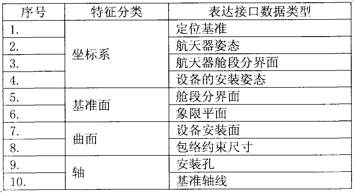
[0016] According to the characteristics of the spacecraft based on the feature interface data of the 3D model, the mechanical overall expresses various interfaces with the definition of different features in combination with feature classification, see Table 1 for details.

[0017] Table 1 Summary table of naming features of 3D model of spacecraft model system

[0018]

[0019] The upper-level model packs the output interface data into a data package and publishes it, and the lower-level model realizes automatic association with the interface data of the upper-level model by copying the interface data package released by the upper-level model...


PUM


Abstract

The invention provides a naming method for complex system characteristics. A machine assembly formulates and selects the standard and uniform templates according to the requirements, issues the templates to multiple development organizations including an assembly, a structure and mechanism subsystem, a thermal control subsystem, other subsystems, the process design department and the like, and issues the templates to related single-machine units through all collaborative units. For space vehicles, the machine assembly plans and formulates interface classifications of a three-dimensional model on the basis of characteristics of three-dimensional model characteristic transitional information and through combination with the characteristic classifications. The machine assembly formulates interface standards for the related collaborative units, and the characteristic naming method achieved after characteristic expression is adopted for standard interface information. The related collaborative units conduct model characteristic naming according to the interface standards, and in the collaborative design process, accuracy of model information reading is achieved, effectiveness of information interaction conducted on the basis of model characteristics is achieved and effective control over the whole technical state is achieved. By means of the naming method, accuracy and effectiveness of interface information interaction in the collaborative design process are achieved, effective control over the technical state is achieved, readability of model data information in the collaborative design process is improved, and meanwhile collaborative design efficiency is improved.

Description

technical field [0001] The invention belongs to the field of three-dimensional digitization of spacecraft, and in particular relates to a control naming method of a data interface. Background technique [0002] The design and development of spacecraft are characterized by more and more functional requirements, more and more complex interface relationships between systems, and higher and higher requirements for design quality. At present, the three-dimensional digital collaborative design method is adopted to meet the design and development requirements of spacecraft. Participating units in the 3D digital collaborative design of spacecraft include mechanical overall, structure and mechanism subsystems, thermal control subsystems and other subsystems, and process design departments. The data interface relationship between collaborative units is complex. At the same time, in the collaborative design process, a wide variety of models are involved, mainly including spacecraft co...

Claims


Application Information

Patent Timeline
IPC IPC(8): G06F17/50
Inventor 刘刚金玮玮李振义杨永彬侯向阳刘晓震沈锋钢
Owner BEIJING SPACE TECH RES & TEST CENT
Learn More