Inspection apparatus and method

A technology for inspection equipment and detectors, applied in optomechanical equipment, microlithography exposure equipment, spectrum investigation, etc., can solve problems such as process influence height measurement, and achieve the effect of simple optical structure

Inactive Publication Date: 2014-12-17
ASML NETHERLANDS BV
View PDF8 Cites 23 Cited by
  • Summary
  • Abstract
  • Description
  • Claims
  • Application Information

AI Technical Summary

Problems solved by technology

[0010] A problem in photolithography processes is often that the height measurements used to control the transfer of the pattern to the substrate can be unpredictably affected by process-dependent influences

Method used


Image

  • Inspection apparatus and method
  • Inspection apparatus and method
  • Inspection apparatus and method

Examples


Embodiment Construction

[0048] This specification discloses one or more embodiments that incorporate the features of this invention. The disclosed embodiments are merely illustrative of the invention. The scope of the invention is not limited to the disclosed embodiments. The invention is defined by the appended claims.

[0049] Embodiments are described, and references in the specification to "one embodiment," "an embodiment," "an exemplary embodiment," etc. indicate that the described embodiments may include particular features, structures, or characteristics, But not every embodiment must include a specific feature, structure or characteristic. Moreover, these phrases are not necessarily referring to the same embodiment. Furthermore, when particular features, structures or characteristics are described in conjunction with an embodiment, it should be understood that it is within the purview of those skilled in the art to implement those features, structures or characteristics in combination with...


PUM

PropertyMeasurementUnit
wavelengthaaaaaaaaaa
angle of incidenceaaaaaaaaaa

Abstract

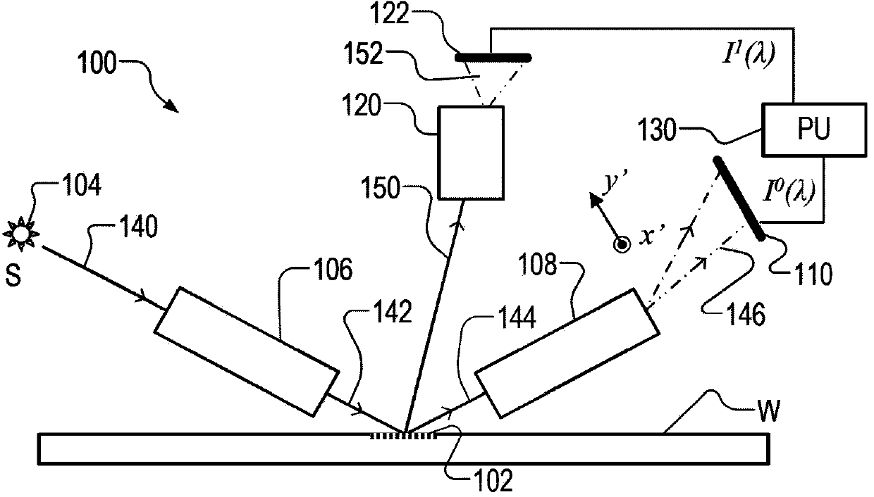
A spectroscopic scatterometer detects both zero order and higher order radiation diffracted from an illuminated spot on a target grating. The apparatus forms and detects a spectrum of zero order (reflected) radiation, and separately forms and detects a spectrum of the higher order diffracted radiation. Each spectrum is formed using a symmetrical phase grating, so as to form and detect a symmetrical pair of spectra. The pair of spectra can be averaged to obtain a single spectrum with reduced focus sensitivity. Comparing the two spectra can yield information for improving height measurements in a subsequent lithographic step. The target grating is oriented obliquely so that the zero order and higher order radiation emanate from the spot in different planes. Two scatterometers can operate simultaneously, illuminating the target from different oblique directions.; A radial transmission filter reduces sidelobes in the spot and reduces product crosstalk.

Description

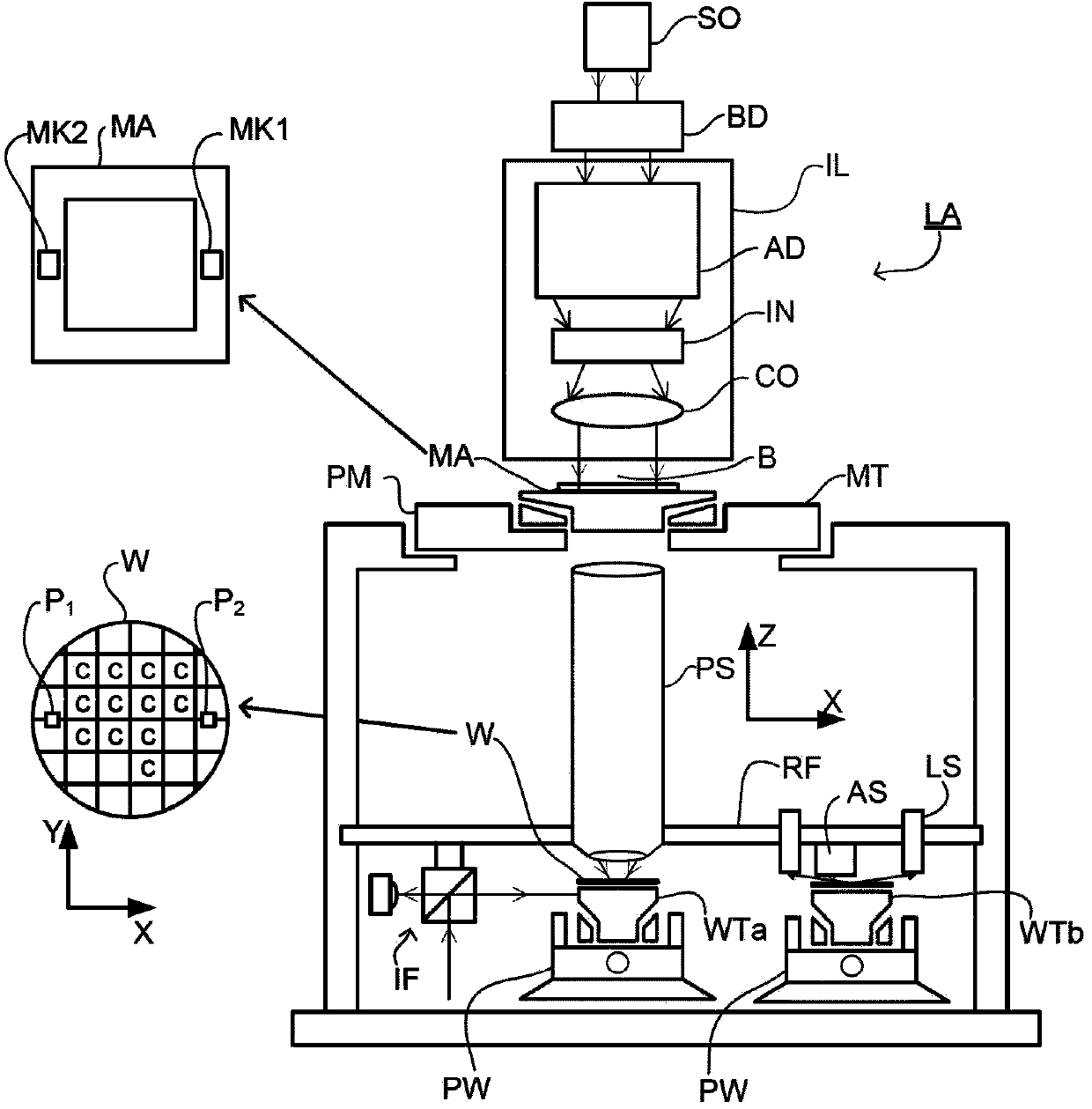
[0001] Cross References to Related Applications [0002] This application claims priority to US Provisional Application 61 / 601,156, filed February 21, 2012, which is hereby incorporated by reference in its entirety. technical field [0003] The present invention relates to inspection apparatus and methods that can be used, for example, to manufacture devices by photolithographic techniques. Background technique [0004] A lithographic apparatus is a machine that applies a desired pattern onto a substrate, usually onto a target portion of the substrate. A lithographic apparatus may, for example, be used in the manufacture of integrated circuits (ICs). In this case, a patterning device, alternatively called a mask or reticle, may be used to create the circuit pattern to be formed on the individual layers of the IC. The pattern can be transferred onto a target portion (eg, a portion comprising one or several dies) on a substrate (eg, a silicon wafer). Transfer of the patter...

Claims


Application Information

Patent Timeline
Patent Type & Authority Applications(China)
IPC IPC(8): G03F7/20G01N21/956
CPCG03F7/20G03F7/70616G03F7/70625G03F7/70633G03F9/7026G01N21/956G01N21/4788G01N21/9501G01N21/95607G01J3/44G03F9/00H01L21/027G01J3/4412G03F7/70591G02B5/205
Inventor A·登博夫
Owner ASML NETHERLANDS BV
Why Eureka
Try Eureka