Permanent magnet motor

A technology of permanent magnets and motors, applied in magnetic circuits, synchronous motors with stationary armatures and rotating magnets, electrical components, etc., can solve the problem of increased q-axis inductance, increased high-order harmonic magnetic flux, and torque ripple Increase and other problems, to achieve the effect of reducing torque ripple

Active Publication Date: 2014-12-17
AIDA ENG LTD +1
View PDF4 Cites 13 Cited by
  • Summary
  • Abstract
  • Description
  • Claims
  • Application Information

AI Technical Summary

Problems solved by technology

[0007] (4) Because the reluctance torque is used in principle, the higher harmonic magnetic flux passing through the core increases, so the torque ripple is considered to increase
Therefore, the q-axis inductance Lq proportional to the q-axis magnetic flux Φq also becomes larger

Method used


Image

  • Permanent magnet motor
  • Permanent magnet motor
  • Permanent magnet motor

Examples


Embodiment Construction

[0061] Hereinafter, embodiments of the present invention will be described based on the drawings.

[0062] (Example)

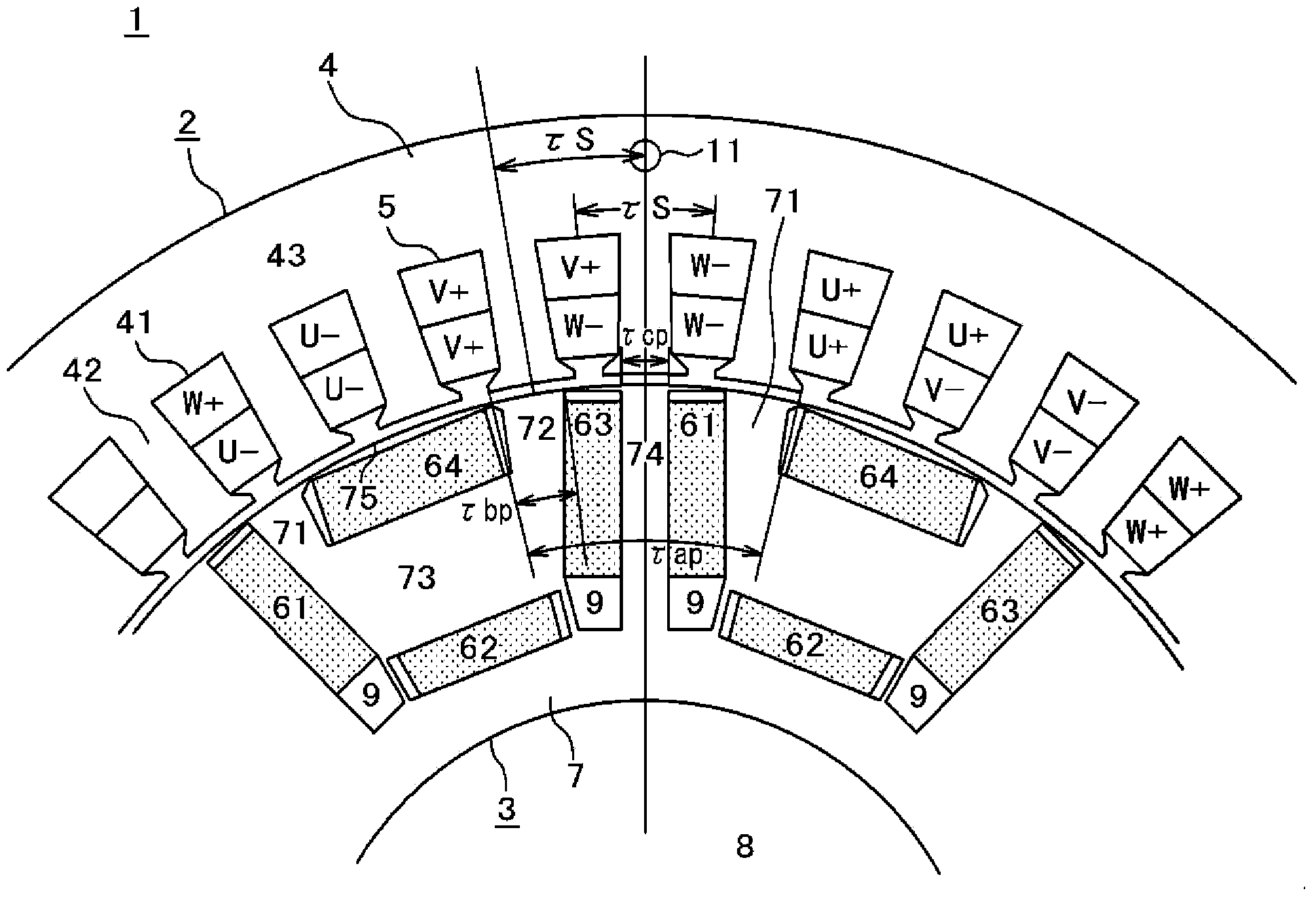
[0063] figure 1 A sectional view of main parts showing a permanent magnet motor according to an embodiment of the present invention.

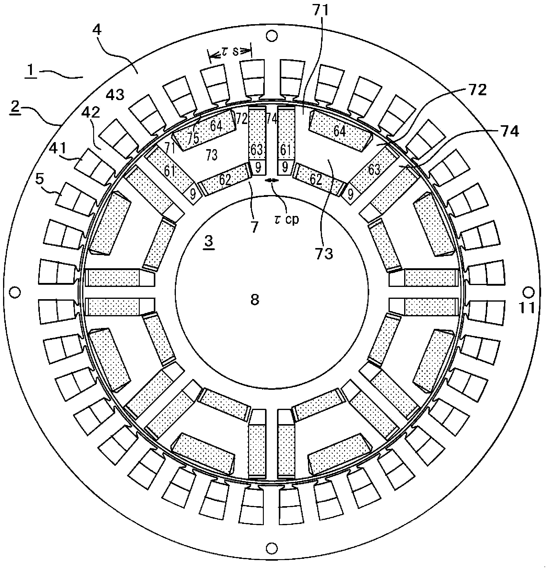
[0064] figure 2 A diagram showing the overall configuration of a permanent magnet motor according to an embodiment of the present invention.

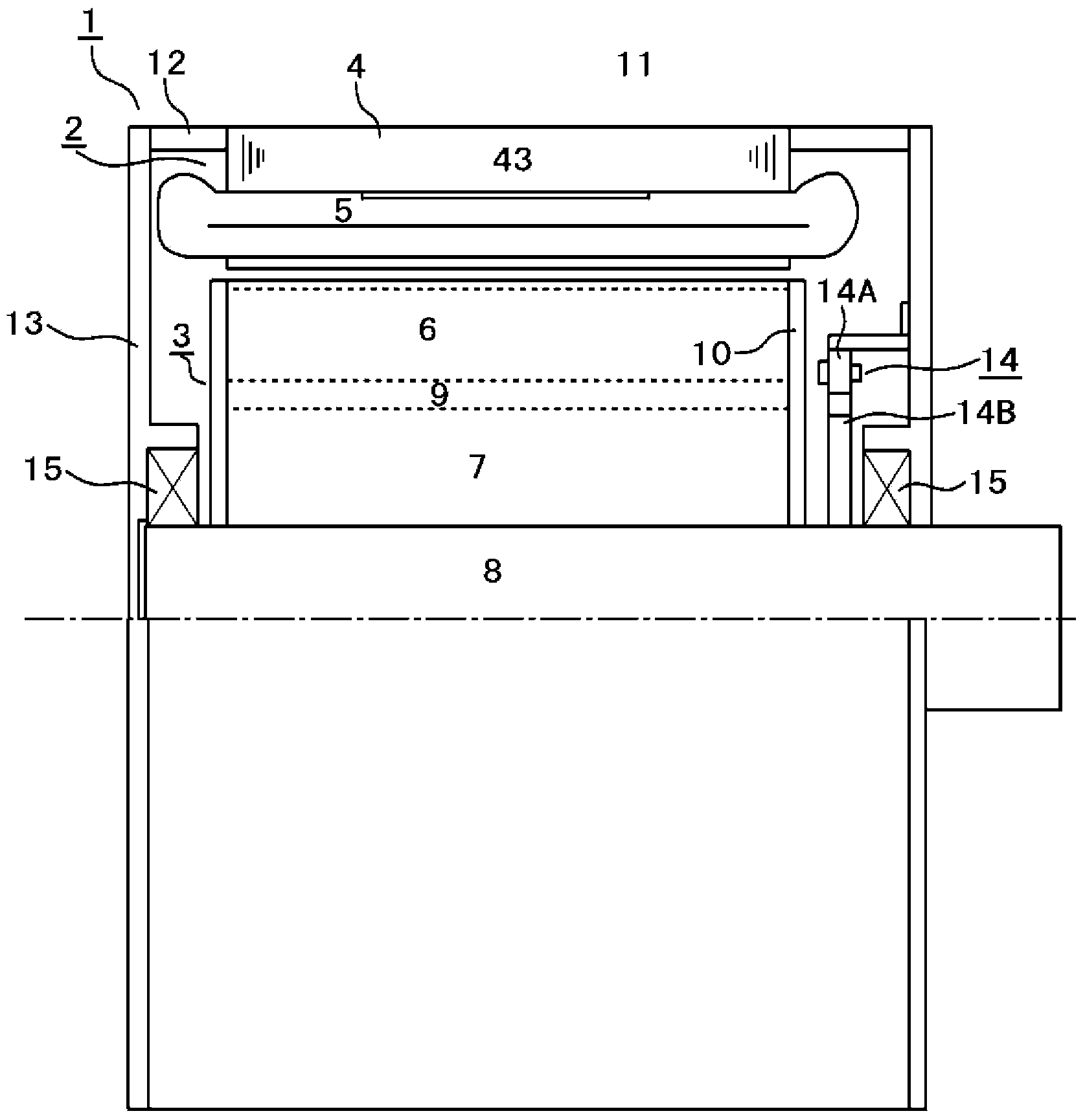
[0065] image 3 An axial sectional view of a permanent magnet motor according to an embodiment of the present invention is shown.

[0066] figure 1 will be figure 2 A diagram showing an enlarged representation of the bipolar portion. In the drawings, only numerals represent components, and underlines under the numerals represent aggregates of components.

[0067] In the drawing, a permanent magnet motor 1 is composed of a stator (stator) 2 and a rotor (permanent magnet rotor) 3 . The stator 2 is mainly composed of a stator core (fixed core) 4 and a stator coil (stator coil) ...


PUM


Abstract

The objective of the present invention is, in a permanent magnet motor using a ferrite magnet, to maximize torque due to the permanent magnet and torque due to the reluctance torque while minimizing the torque ripple ratio. A P-pole-implanted permanent magnet rotator containing a ferrite magnet in a laminated silicon steel sheet, wherein the permanent magnet motor is characterized in disposing, at one pole, a U-shaped permanent magnet comprising three parts, and, at the outer periphery of the U-shaped magnet, one outer-periphery permanent magnet disposed longitudinally in the peripheral direction, to generate permanent magnet torque, and also being provided with: at one pole, the permanent magnet rotator configured to generate reluctance torque using two salient poles formed between the U-shaped permanent magnet and the outer-periphery permanent magnet, and one central salient pole formed between the adjacent poles; and a stator comprising an M-phase stator winding that is a distributed winding, and a stator core having Ns slots, the ratio of Ns/P/M being a common fraction, and when the width of the center salient pole is set to [tau]cp and the slot pitch of the stator core is set to [tau]s, [tau]cp being smaller than [tau]s.

Description

technical field [0001] The present invention relates to a permanent magnet motor structure, which uses an inexpensive rectangular parallelepiped ferrite magnet and targets a permanent magnet motor mainly having reluctance torque, and is capable of generating large torque with low torque ripple. Background technique [0002] In permanent magnet motors that generate high torque so far, it is possible to achieve both high torque and low torque ripple by using a so-called surface magnet type motor structure that uses high-performance neodymium magnets and arranges magnets on the surface of the rotor. Permanent magnet motors have already been put into practical use. However, since neodymium magnets are expensive and difficult to obtain in recent years, research and development of permanent magnet motors using ferrite magnets has been ongoing. Ferrite magnets are less than 1 / 10 cheaper than neodymium magnets, but have the following disadvantages. Their performance is less than 1 / ...

Claims


Application Information

Patent Timeline
Patent Type & Authority Applications(China)
IPC IPC(8): H02K21/14
CPCH02K1/2766H02K1/2773H02K21/16H02K2213/03
Inventor 田岛文男山口芳弘长濑博八原昌尚藤泽劝也
Owner AIDA ENG LTD
Why Eureka
Try Eureka