
Cloth separation device

A separation device and fabric technology, applied in the direction of sewing clothes tools, etc., can solve the problems of complex structure of fabric separation device, affect production efficiency, unfavorable installation and maintenance, etc., achieve simple structure, improve production efficiency, and facilitate assembly and maintenance.

Active Publication Date: 2014-12-24
JACK SEWING MASCH CO LTD
View PDF6 Cites 6 Cited by
  • Summary
  • Abstract
  • Description
  • Claims
  • Application Information

AI Technical Summary

Problems solved by technology

In addition, the air suction method also needs to install supporting air suction equipment on the manipulator. The air suction equipment needs to be driven by energy, which not only makes the structure of the entire material separation device complicated, is not conducive to installation and maintenance, but also increases production costs and consumes more. energy
In addition to the air suction method, there is also a separation method of rubbing or clamping the fabric with the fingers of the manipulator, but this method of fabric separation often brings up multiple layers of fabric at one time, affecting production efficiency

Method used


Image

  • Cloth separation device
  • Cloth separation device
  • Cloth separation device

Examples


Embodiment Construction

[0026] Embodiments of the present invention are described below through specific examples, and those skilled in the art can easily understand other advantages and effects of the present invention from the content disclosed in this specification. The present invention can also be implemented or applied through other different specific embodiments, and various modifications or changes can be made to the details in this specification based on different viewpoints and applications without departing from the spirit of the present invention.

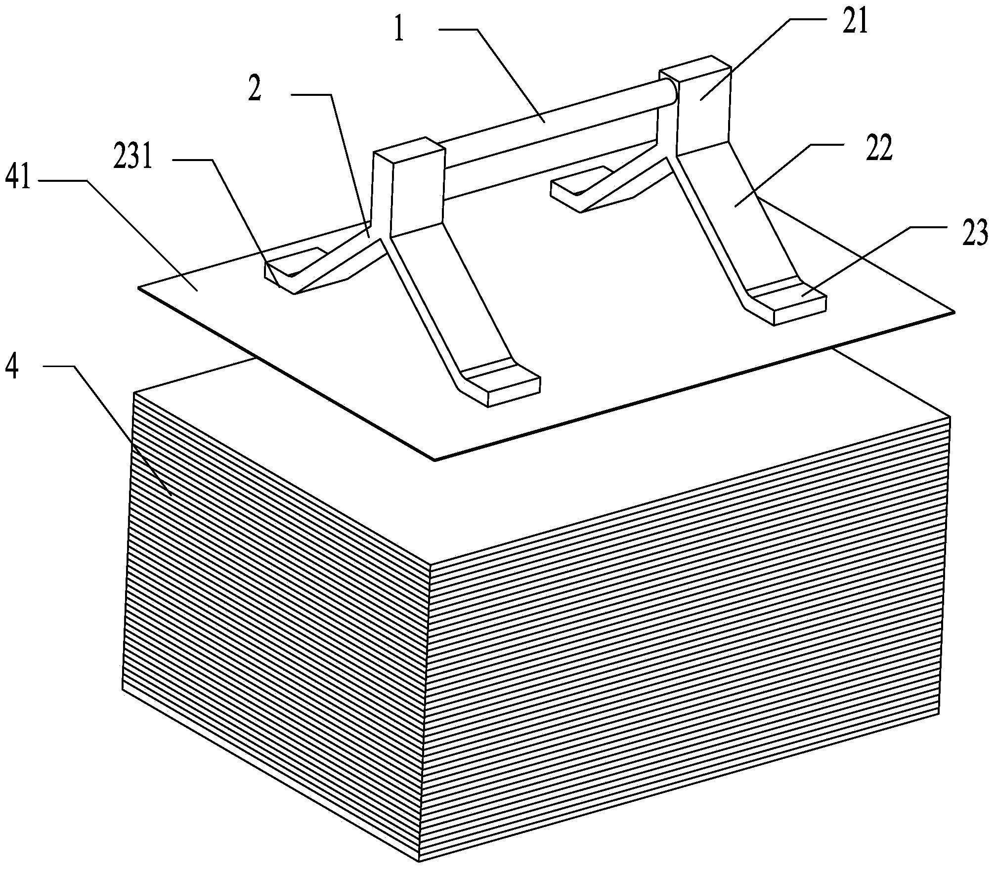
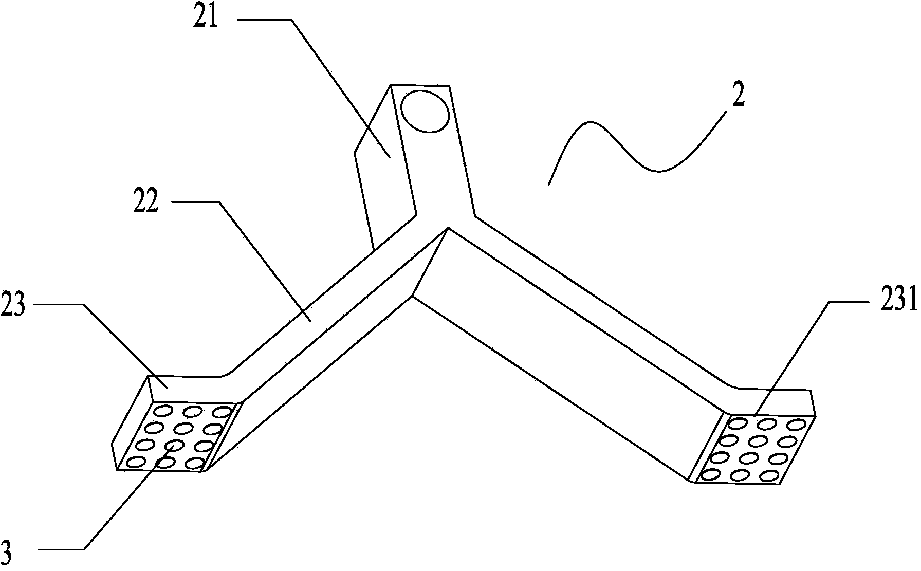
[0027] see Figure 1 to Figure 3 . It should be noted that the diagrams provided in this embodiment are only schematically illustrating the basic idea of ​​the present invention, and only the components related to the present invention are shown in the diagrams rather than the number, shape and shape of the components in actual implementation. Dimensional drawing, the type, quantity and proportion of each component can be changed arbitrarily ...


PUM


Abstract

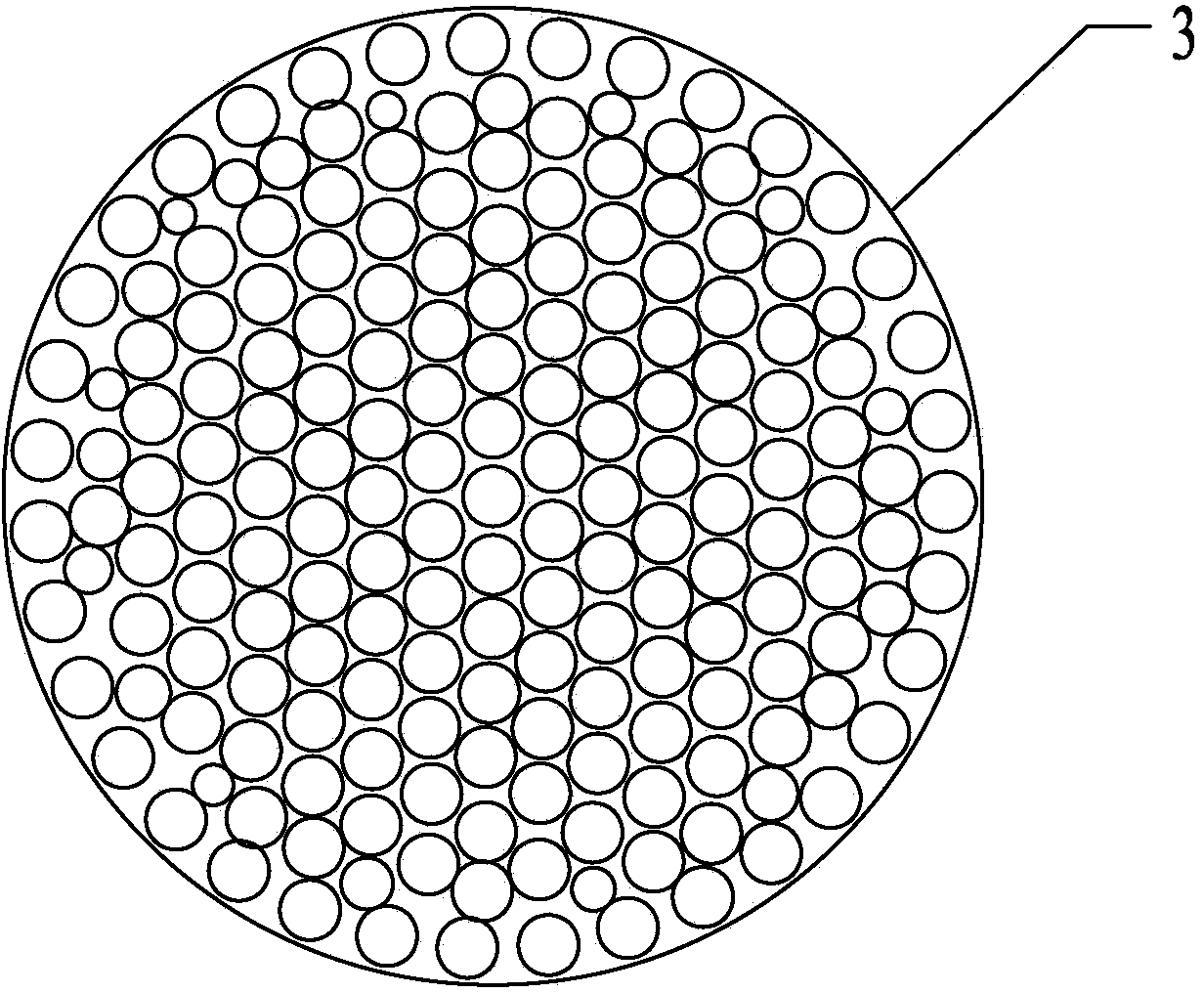
The invention provides a cloth separation device. The cloth separation device comprises a connecting rod which is fixedly connected with a manipulator, wherein the connecting rod is provided with at least two suction brackets; the ends, connected with the connecting rod, of the suction brackets are connecting ends; the other ends of the suction brackets are suction ends; the suction ends are provided with suction faces which are opposite and parallel to the plane where cloth is positioned; the suction faces are provided with suction units; the suction units are made of a bionic gecko foot material. The suction brackets are arranged on the connecting rod in a sleeving manner; the relative distance between every two suction brackets is adjustable. The suction brackets are provided with two bracket arms; the two bracket arms are opened opposite to each other from the connecting ends and are positioned on the two sides of the connecting rod respectively; the bottom ends of the bracket arms extend in the direction parallel to the cloth to form the suction ends. The suction units are circular or rectangular and are transversely and vertically arranged on the suction faces in sequence at an interval. The cloth separation device has a simple structure; no external force is required for driving in the cloth adsorption process, so that the energy is favorably saved; the highly breathable cloth can be accurately separated layer by layer, so that the production efficiency is improved.

Description

technical field [0001] The invention relates to the technical field of sewing equipment, in particular to a cloth separating device. Background technique [0002] In the garment manufacturing process, in order to ensure the cutting quality and cutting efficiency, the garment enterprises stack the multi-layer fabrics neatly in the cutting area, and use the cutting bed to uniformly cut them. After the cutting is finished, the cut fabrics are separated layer by layer by the robot arm, and then placed in the sewing area for the next step of sewing. [0003] The method of separating cloth in the prior art often adopts the cloth suction method, and the common cloth suction method is the air suction method, and the air suction method is mainly divided into two methods: vacuum suction and air suction. Due to the large gaps between the textures of commonly used fabrics and good air permeability, it is difficult to achieve the adsorption of commonly used fabrics by simply using the a...

Claims


Application Information

Patent Timeline
IPC IPC(8): A41H43/02
Inventor 展晓珺钱坤陈志强韩安太
Owner JACK SEWING MASCH CO LTD
Learn More