
CT system, CT system scanning positioning method and CT system calibration method

A technology of CT scanning and calibration method, which is applied in the field of CT system, can solve problems such as troublesome operation and long time consumption, and achieve the effects of improving accuracy, shortening scanning time, and reducing radiation dose

Active Publication Date: 2014-12-24
GE MEDICAL SYST GLOBAL TECH CO LLC
View PDF2 Cites 36 Cited by
  • Summary
  • Abstract
  • Description
  • Claims
  • Application Information

AI Technical Summary

Problems solved by technology

Although the X-ray radiation dose of this X-ray imaging is within the safe range, further reducing the radiation dose to patients during the scanning positioning process is still the pursuit of the CT imaging technology field.
[0004] In addition, the existing positioning scanning relies on laser lights for positioning, which takes a long time and is troublesome to operate

Method used


Image

  • CT system, CT system scanning positioning method and CT system calibration method
  • CT system, CT system scanning positioning method and CT system calibration method
  • CT system, CT system scanning positioning method and CT system calibration method

Examples


Embodiment Construction

[0071] Hereinafter, specific embodiments for implementing the present invention will be described in detail with reference to the drawings. However, it should be understood that the present invention is not limited to the following specific embodiments.

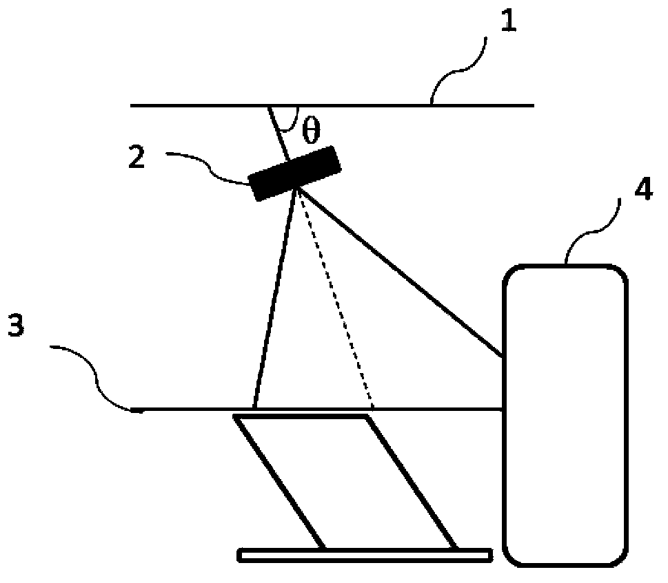
[0072] figure 1 It shows a schematic diagram of the composition of an embodiment of the CT system according to the present invention. In this embodiment, the CT system includes a 3D camera 2, a hospital bed 3, a CT scanning and imaging device 4, and a processing unit (not shown in the figure). The hospital bed 3 is a movable hospital bed with adjustable bed height and horizontal movement for supporting the patient to be scanned on it. The 3D camera 2 is used to shoot images of the patient to be scanned on the hospital bed 3. The 3D camera mentioned in this article refers to a camera that can simultaneously collect RGB data and depth data. Generally, the 3D camera 2 is located in the space above the hospital bed 3, for exampl...


PUM


Abstract

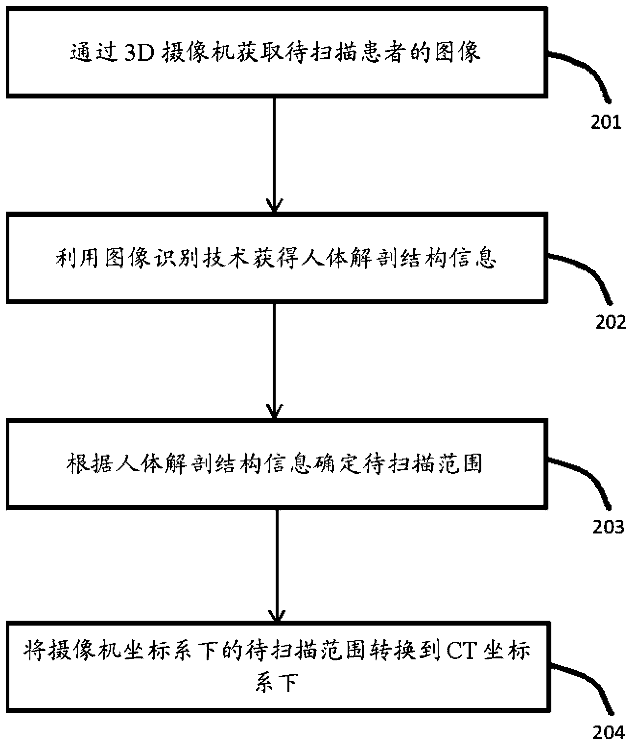
The invention relates to a CT system, a CT system scanning positioning method and a CT system calibration method. The CT system comprises a hospital bed, CT scanning and imaging equipment, a 3D video camera and a processing unit. The hospital bed is used for supporting a patient to be scanned on the hospital bed. The CT scanning and imaging equipment is used for conducting CT scanning and imaging on the patient to be scanned. The 3D video camera is used for shooting a 3D image of the patient to be scanned on the hospital bed. The processing unit is used for acquiring human anatomy structural information of the patient to be scanned according to the 3D image shot by the 3D video camera so as to determine the range to be scanned and for converting the range to be scanned of the 3D video camera under a space coordinate system to the range to be scanned of the CT scanning and imaging equipment under a space coordinate system. The CT scanning and imaging equipment conducts scanning and imaging on the patient to be scanned according to the converted range to be scanned of the CT scanning and imaging equipment under the space coordinate system. By means of the CT system, the CT system scanning positioning method and the CT system calibration method, the precision of the scanned range can be improved, scanning time is shortened, and radiation dosage is lowered.

Description

Technical field [0001] The invention relates to the field of CT imaging technology, in particular to a CT system, its scanning positioning method and a calibration method. Background technique [0002] When using a CT system to scan and image a patient to be scanned, it usually includes two stages: the first stage is the scan positioning stage, that is, the stage to determine the range to be scanned, which is used to determine the start position, end position and gantry of the scan The inclination angle; the second stage is the stage of real scanning imaging according to the determined range to be scanned. [0003] Currently, X-ray imaging is used to determine the range to be scanned when scanning and positioning in the first stage. Although the X-ray radiation dose of this X-ray imaging is within the safe range, further reducing the radiation dose to the patient during the scanning and positioning process is still a constant pursuit in the field of CT imaging technology. [0004] ...

Claims


Application Information

Patent Timeline
Patent Type & Authority Applications(China)
IPC IPC(8): A61B6/03
Inventor 王秉欣贾磊叶芷魏东
Owner GE MEDICAL SYST GLOBAL TECH CO LLC
Learn More